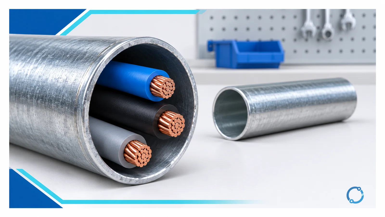
Short answer: Conduit fill is the percentage of a raceway’s internal cross-sectional area occupied by all conductors and cables installed in it. Under NEC Chapter 9 Table 1, the normal maximum is 53% for one conductor, 31% for two conductors, and 40% for three or more conductors. Limiting fill leaves working space for pulling conductors without damaging insulation, reduces crowding and friction, and preserves practical room for the completed wiring system.
The manual calculation has three parts: obtain each conductor’s actual insulated cross-sectional area, add every item that counts toward fill, and compare that total with the allowable area for the selected raceway and conductor count. Do not compare bare copper area with conduit area, and do not assume that a conductor’s AWG size is its insulated outside area.
This article explains that hand method. It does not select a raceway system, specify installation technique or replace the locally adopted National Electrical Code (NEC), project documents, listing instructions or authority having jurisdiction.
The conduit fill formula
The basic relationship is:
Conduit fill (%) = total conductor area / conduit internal area x 100
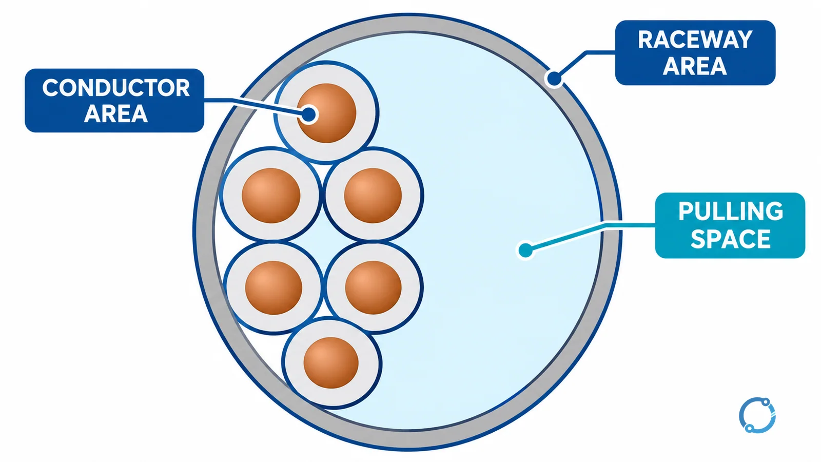
The numerator is the sum of the cross-sectional areas of the insulated conductors, cables and other items that Chapter 9 requires to be included. The denominator is the raceway’s internal cross-sectional area. Both quantities must use the same area unit, normally square inches in the NEC tables.
If the task is only to check compliance, it is often faster to compare the conductor total directly with the allowed fill area in Chapter 9 Table 4:
Total conductor area <= allowable raceway fill area
That comparison avoids calculating the raceway’s full internal area and multiplying it by the permitted percentage. Table 4 has already done that step for standard raceway trade sizes and fill percentages.
NEC Chapter 9 Table 1 fill limits
Chapter 9 Table 1 assigns the following maximum occupied percentages for complete conduit or tubing systems under its normal scope:
| Number of conductors or cables | Maximum occupied area |
|---|---|
| 1 | 53% |
| 2 | 31% |
| 3 or more | 40% |
These percentages are not a quality ranking. The lower two-conductor percentage reflects the geometry of two round objects inside a round raceway. Three or more conductors can pack differently, so the rule returns to 40%. Using 53% whenever the raceway looks spacious is incorrect; conductor count determines which percentage applies.
The count is also not limited to ungrounded conductors. Equipment grounding or bonding conductors installed in the raceway count toward fill. If the grounding conductor is insulated, use the applicable insulated area. If it is bare and permitted, use the applicable actual area under the adopted-code method. A grounding conductor may not be a current-carrying conductor for ampacity adjustment, but it still occupies physical space.
Chapter 9 contains notes and special cases beyond the three ordinary percentages. This page intentionally does not reproduce those exceptions. Always verify the adopted NEC edition and the exact installation condition before treating a quick calculation as the final code decision.
Which NEC tables supply the inputs?
The calculation uses three Chapter 9 tables for three different jobs.
Table 1: choose the permitted percentage
First count the conductors or cables that must be included in fill. One conductor uses 53%, two use 31%, and three or more use 40%. This establishes the applicable fill column for the raceway.
Table 5 or Table 5A: find conductor area
Table 5 gives dimensions and areas for insulated conductors by conductor type and size. Table 5A covers compact aluminum building wire. The insulation designation matters because two conductors with the same AWG size can have different outside diameters and cross-sectional areas.
This is why the AWG wire size chart cannot replace Table 5 for fill. AWG identifies the metallic conductor size; conduit fill must account for the finished insulated conductor or cable that physically occupies the raceway.
For mixed conductors, look up each size and insulation type separately, multiply each area by its quantity, and add the subtotals. If a cable or conductor is not represented by the applicable table, use the dimension method allowed by the adopted code and the verified product construction rather than guessing from nominal trade size.
Table 4: find allowable raceway area
Table 4 lists dimensions and usable fill areas for each raceway type and trade size. Select the correct raceway family first: electrical metallic tubing (EMT), rigid metal conduit, intermediate metal conduit and nonmetallic raceways do not share one universal internal area.
Then read the column that matches the Table 1 percentage. For three or more conductors, compare the conductor total with the 40% value. Do not compare it with the raceway’s full internal area or with a value from a different raceway type.
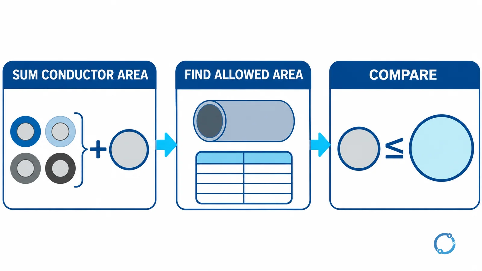
The three-step manual workflow
Step 1: add the conductor areas
Build a small worksheet with conductor type, size, quantity, individual area and subtotal. Include every conductor or cable that counts toward raceway fill. Keep the units visible so square inches are not mixed with square millimeters.
Step 2: find the allowable raceway area
Use the number of conductors to select 53%, 31% or 40%, then find the selected raceway type and trade size in Table 4. Record the allowable area, not merely the nominal conduit size.
Step 3: compare and document
The raceway passes the area comparison when the total conductor area is no greater than the applicable Table 4 allowable area. Document the NEC edition, table rows, conductor insulation type, raceway type and arithmetic. That record makes the result reviewable and prevents a later substitution from silently invalidating it.
Worked example: three 12 AWG THHN conductors in 1/2-inch EMT
Consider a stated example with three 12 AWG copper conductors, each using THHN insulation, installed in 1/2-inch EMT. The inputs are fixed to the Chapter 9 table values specified for this example.
1. Determine the percentage
There are three conductors, so Chapter 9 Table 1 uses the 40% fill limit.
2. Add the conductor areas
Chapter 9 Table 5 gives an approximate area of 0.0133 in² for one 12 AWG THHN conductor.
3 x 0.0133 in² = 0.0399 in²
The total occupied conductor area is therefore 0.0399 in².
3. Find the EMT allowance
Chapter 9 Table 4 gives 0.122 in² as the 40% fill area for 1/2-inch EMT.
Compare the two values:
0.0399 in² < 0.122 in²
The three conductors fit within the stated 40% area limit. Expressed as a share of the permitted 40% area, the installation uses:
0.0399 / 0.122 x 100 = 32.70%
That 32.70% is the portion of the allowable 40% area consumed, not the percentage of the raceway’s complete internal area. Keeping those denominators separate avoids a misleading result.
Maximum equal-size conductor count
For equal 12 AWG THHN conductors in the same raceway, divide the 40% allowable area by the individual conductor area:
0.122 in² / 0.0133 in² = 9.17
Only whole conductors can be installed, so use the integer that does not exceed the area:
floor(0.122 / 0.0133) = 9 conductors
A direct check confirms it:
9 x 0.0133 in² = 0.1197 in²
0.1197 in² < 0.122 in²
Ten would require 0.1330 in², which exceeds the stated allowance. The area result is nine for this exact conductor construction and raceway input. It does not automatically approve ampacity, conductor grouping, pulling difficulty, bend geometry, terminal capacity or the complete installation.
Conduit fill is not ampacity adjustment
Raceway fill and conductor ampacity answer different questions. Fill limits physical occupation of the raceway. Ampacity adjustment addresses heating when conductors operate together.
Where more than three current-carrying conductors are installed in a raceway or cable, NEC Table 310.15(C)(1) adjustment can apply within its stated scope and exceptions. A grounding conductor counts for fill but normally is not counted as a current-carrying conductor for this adjustment. The wire size guide explains how ampacity, temperature conditions and voltage drop remain separate verification gates.
Distance also does not change the Chapter 9 fill percentage, but it can change electrical performance and pulling conditions. Check the separate voltage drop calculation when circuit length is part of the design.
How to handle mixed conductor sizes
The equal-size example can use one division because every conductor has the same Table 5 area. A mixed raceway needs a subtotal for each conductor construction. For example, the worksheet should have one row for each combination of insulation type and AWG size, not merely one row for all copper conductors.
Use this sequence:
- Record the exact insulation or cable designation for every item.
- Look up the applicable cross-sectional area for each size and construction.
- Multiply each individual area by its quantity.
- Add all subtotals, including grounding or bonding conductors that occupy the raceway.
- Count the conductors or cables under the applicable Table 1 rules to select the permitted percentage.
- Compare the combined area with the correct Table 4 value for the actual raceway type and trade size.
Do not average conductor areas. A large conductor and several small conductors must retain their actual areas in the sum. Also do not use the equal-size maximum count from Informative Annex C when the raceway contains mixed sizes; the direct area calculation is the transparent method.
If a specified conductor changes from one insulation construction to another during procurement, repeat the lookup. The metallic AWG may be unchanged while the insulated outside area changes enough to alter the fill result.
What a passing fill calculation does not approve
Passing the area comparison confirms only the stated Chapter 9 fill check. It does not prove that the pull can be made without excessive tension, that bend limits and box fill are satisfied, or that the raceway and conductors are suitable for the location. It also does not establish ampacity, overcurrent protection, terminal temperature compatibility, voltage drop or fault-current performance.
Treat the fill worksheet as one documented gate in the circuit design. A useful record names the conductor construction, quantities, raceway type, trade size, NEC edition and table values. If any of those inputs changes, the result should be recalculated rather than carried forward by assumption.
Common conduit fill mistakes
Using outside diameter as if it were area
Diameter and area are different quantities. If an actual diameter must be used, convert it to circular area with the correct formula and code method. Do not add diameters and compare the sum with conduit diameter.
Forgetting the equipment grounding conductor
An equipment grounding or bonding conductor occupies space even though it does not normally carry load current. Include its applicable area in the fill worksheet.
Using 53% for three or more conductors
The 53% value applies to one conductor. Three or more use 40% under Chapter 9 Table 1’s ordinary rule. Selecting the wrong column can overstate available space.
Mixing conductor or raceway types
THHN, XHHW and other insulation constructions can have different areas at the same AWG. EMT and other raceways can have different internal areas at the same nominal trade size. Every lookup must match the item actually specified.
Further reading
Use the VIOX conduit fill calculator to check a manual result after entering the same conductor type, size, quantity and raceway assumptions. A calculator can speed arithmetic, but it cannot decide which conductors count, which NEC edition applies or whether ampacity adjustment and installation rules are also satisfied.
FAQ
What is the NEC conduit fill limit for three or more conductors?
The ordinary Chapter 9 Table 1 limit is 40% of the raceway’s internal cross-sectional area for three or more conductors or cables. Verify the adopted NEC edition, table notes and any special installation condition before applying it.
Do equipment grounding conductors count for conduit fill?
Yes. An equipment grounding or bonding conductor installed in the raceway occupies physical space and must be included using its applicable insulated or bare cross-sectional area.
Which NEC tables are used for conduit fill calculation?
Chapter 9 Table 1 provides the permitted fill percentage, Table 5 or 5A provides conductor dimensions and areas, and Table 4 provides raceway dimensions and allowable fill areas by raceway type and trade size.
How many 12 AWG THHN conductors fit in 1/2-inch EMT in the stated example?
Using 0.0133 in² per conductor and a 0.122 in² 40% EMT allowance, floor(0.122 / 0.0133) = 9. This area result does not replace ampacity adjustment or other installation checks.
Is conduit fill the same as conductor ampacity derating?
No. Conduit fill limits physical occupation of the raceway. Ampacity adjustment addresses conductor heating and may apply when more than three current-carrying conductors share a raceway or cable, subject to NEC scope and exceptions.