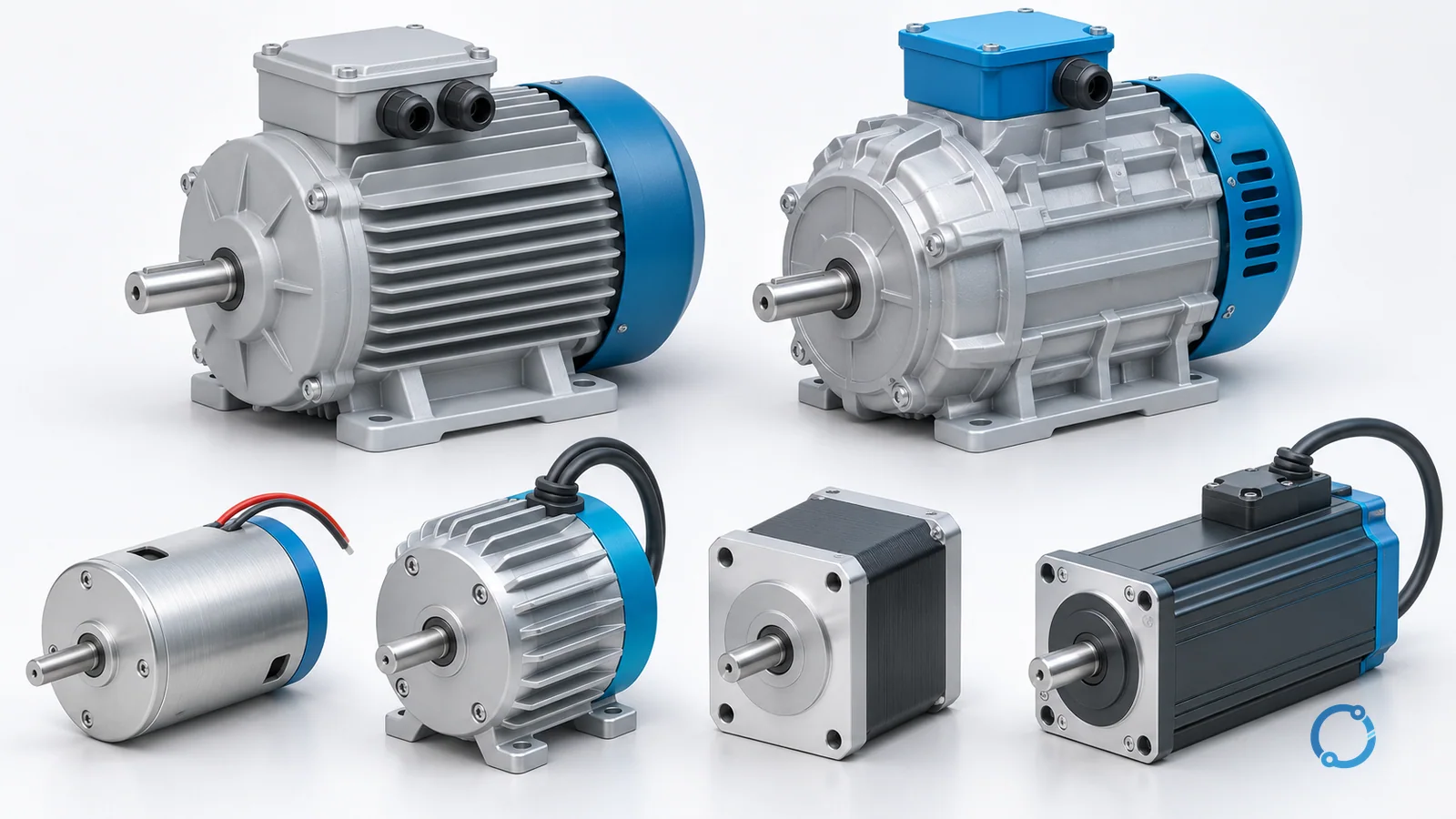
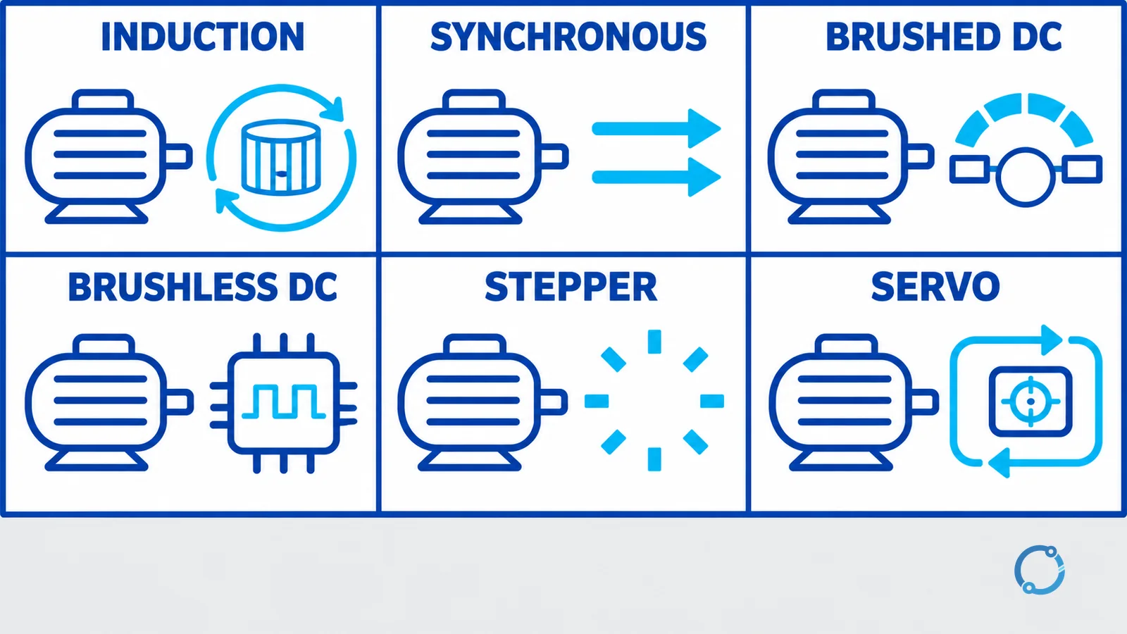
Short answer: Electric motors can be organized into six practical families by supply and rotor or commutation method: AC induction, AC synchronous, brushed DC, brushless DC, stepper and servo motors. The useful distinction is not merely “AC versus DC.” It is how each motor creates rotating torque, what determines its speed, whether it needs electronic commutation or feedback, and whether the load requires continuous rotation or controlled position.
| Motor family | Supply and control | What mainly determines speed | Typical qualitative use |
|---|---|---|---|
| AC induction | AC stator field; direct supply or drive | Supply frequency, pole count and slip | Pumps, fans, conveyors and general industrial drives |
| AC synchronous | AC rotating field plus synchronized rotor field | Supply or drive frequency and pole count | Constant-speed or controlled high-performance drives |
| Brushed DC | DC with mechanical brush-and-commutator switching | Applied voltage, field and load | Simple variable-speed or high-starting-torque duties |
| Brushless DC | DC source with electronic commutation | Electronic commutation rate and control | Compact controlled drives, fans and mobile equipment |
| Stepper | Sequenced phase pulses | Commanded pulse sequence and load response | Incremental positioning and indexing |
| Servo | Closed-loop motor-drive-feedback system | Command plus measured position, speed or torque | Precise dynamic motion and coordinated axes |
This is a terminology and application map, not a sizing procedure. A real motor decision also depends on torque-speed duty, inertia, starting demand, thermal limits, enclosure, environment, control architecture and mechanical load.
One electromagnetic principle, different ways to sustain rotation
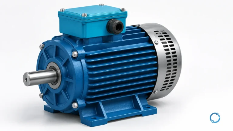
Every electric motor converts electrical energy into mechanical rotation by producing force between magnetic fields and current-carrying conductors. The stator creates or guides a magnetic field; the rotor responds with torque. Motor families differ in how the rotor field is created, how current is switched and how the controller keeps torque pointing in the useful direction.
The full physical sequence belongs in how an electric motor works. Here, that shared principle is only the starting point. The purpose of the classification is to show why motors that all produce shaft rotation behave differently when asked to start, hold speed, reverse, index or follow a position command.
AC induction motors
An induction motor uses alternating current in the stator to create a rotating magnetic field. That moving field induces current in the rotor. The induced rotor current creates its own magnetic effect, and the interaction produces torque.
The rotor must turn slightly slower than the rotating stator field for induction to continue under motoring load. The speed difference is called slip. If the rotor exactly caught the field, relative motion would disappear and the induction mechanism would no longer produce the same torque. Slip therefore is not automatically a defect; it is part of normal induction-motor operation.
Squirrel-cage induction motor
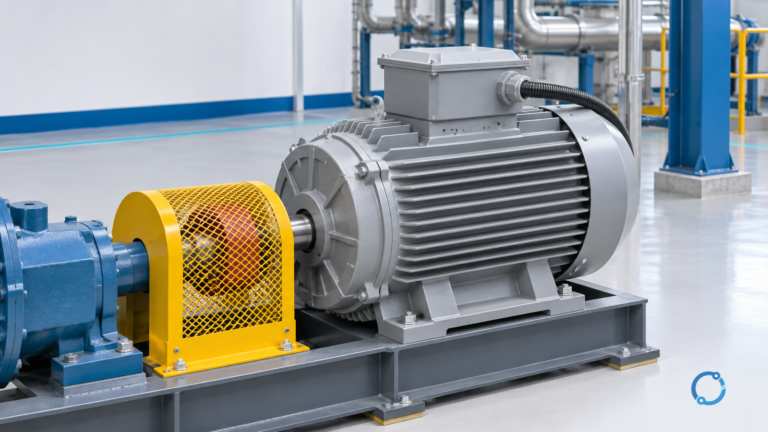
A squirrel-cage rotor uses conductive bars joined by end rings. It has no brush connection to deliver normal operating current into the rotor. The construction is mechanically straightforward and widely used for continuous industrial loads such as pumps, fans and conveyors.
Wound-rotor induction motor
A wound rotor contains rotor windings brought to external connections through slip rings. External rotor-circuit arrangements can influence starting and speed behavior, but they add components and maintenance considerations. This is a construction distinction, not a universal statement that one rotor type is better.
Detailed slip arithmetic is a separate reader task. Use the induction motor slip calculation when measured rotor speed must be compared with synchronous speed.
Synchronous motors
A synchronous motor’s rotor field locks to the rotating stator field in steady operation. Average rotor speed therefore follows synchronous speed rather than running below it by normal induction slip. The rotor field may come from permanent magnets, DC excitation or another synchronous machine design.
That fixed speed relationship is the fundamental difference from an induction motor. It does not mean that every synchronous motor starts directly from standstill without a starting method or electronic drive. Starting architecture depends on the design, and the comparison of motor starting methods handles that separate question.
Synchronous motors suit duties where speed must remain tied to electrical frequency or where a controlled drive and rotor design support precise performance. Their excitation, control and protection requirements can be more involved than those of a basic cage induction motor.
Synchronous speed and pole count
For an AC rotating field, synchronous speed is:
ns = 120f / P
where:
nsis synchronous speed in revolutions per minute;fis electrical frequency in hertz;Pis the number of magnetic poles.
At 60 Hz, the permitted examples are:
| Poles | Calculation | Synchronous speed |
|---|---|---|
| 2 | 120 x 60 / 2 |
3600 rpm |
| 4 | 120 x 60 / 4 |
1800 rpm |
| 6 | 120 x 60 / 6 |
1200 rpm |
| 8 | 120 x 60 / 8 |
900 rpm |
These are synchronous-field speeds. A loaded induction motor normally runs below the corresponding value; a synchronous motor in synchronism runs at it. The table does not predict torque, acceleration or suitability for a load.
Brushed DC motors
A brushed direct-current motor uses a mechanical commutator and brushes to reverse armature-current relationships as the rotor turns. That switching keeps torque acting in a consistent rotational direction. Field production may use permanent magnets or windings, depending on the design.
Brushed DC motors can provide direct, understandable speed and torque control, but the mechanical commutation interface wears and can require inspection. Brush dust, contact condition and commutator maintenance are part of the application boundary. The motor is not defined only by receiving DC; it is defined by its mechanical commutation method.
Brushless DC motors
A brushless DC motor removes the mechanical brush-and-commutator interface and uses electronic switching to energize stator phases in sequence. Rotor position may be measured by sensors or inferred by the controller. Permanent magnets commonly provide the rotor field.
The source feeding the electronic drive may be DC, but the motor windings receive a switched phase pattern. That is why “brushless DC” describes a motor-drive architecture rather than a simple pair of steady DC wires connected directly to a rotating armature. Electronic commutation can reduce brush maintenance and support controlled speed, but it makes the drive and sensing method part of the system.
Stepper motors
A stepper motor advances its magnetic alignment in discrete commanded increments as the controller energizes phases in sequence. The controller can count command pulses to request a position, making the motor useful for indexing, simple positioning and repeatable incremental motion.
Many stepper systems operate open-loop: they assume the rotor completed each commanded step. That can be effective when torque margin, acceleration and load disturbance are controlled, but a missed step may not be detected without feedback. Holding current, resonance and high-speed torque behavior also matter, even though this overview does not calculate them.
A stepper is not automatically less precise than a servo, and a servo is not automatically necessary for every axis. The dedicated stepper versus servo selection guide compares those architectures with the required application inputs.
Servo motors and servo systems
“Servo” describes a closed-loop motion function more than one universal electromagnetic construction. A servo system combines a motor, drive, feedback device and controller. The controller compares commanded motion with measured position, speed or torque and continuously adjusts current to reduce the error.
The motor may be permanent-magnet synchronous, brushless DC or another design suited to dynamic control. Feedback and control bandwidth allow the system to reject disturbances and follow rapid motion commands, which is useful in robotics, machine tools, packaging equipment and coordinated production axes.
That capability requires a matched system. Encoder resolution alone does not determine positioning performance; mechanical stiffness, backlash, inertia, tuning, load disturbance and drive limits also contribute. This page therefore does not convert a motion requirement into a motor rating.
How to compare the motor types qualitatively
For robust continuous rotation
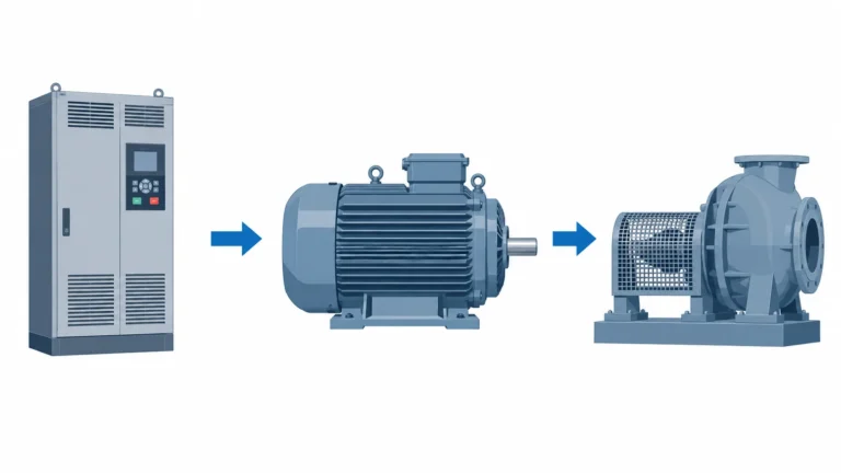
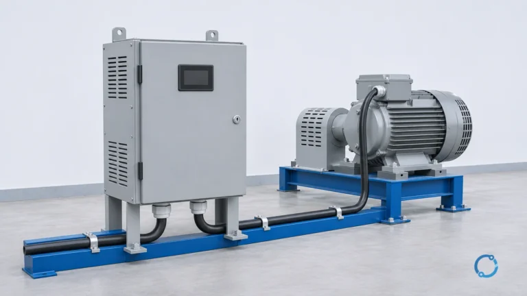
Start with an induction motor when the load requires established industrial continuous rotation and does not need direct position control. If speed must vary during operation, a variable-frequency drive may be part of the system. The VFD definition and operating principle explains that interface without turning this page into a drive-selection guide.
For frequency-locked steady speed
Consider a synchronous motor when operation must follow synchronous speed and the starting or drive system supports the rotor design. “No induction slip” is a speed relationship, not proof that the machine is the best choice for every constant-speed load.
For straightforward DC commutation
A brushed DC motor can fit duties where mechanical commutation and its maintenance are acceptable. A brushless DC architecture fits duties where electronic commutation, compact construction or integrated control is preferred.
For incremental position commands
A stepper can be effective when motion consists of bounded increments and the design provides enough torque margin to avoid losing steps. It is especially useful when a simple open-loop command structure is acceptable.
For closed-loop dynamic motion
A servo system fits axes that must measure and correct position or speed under changing load. Its value comes from the complete feedback loop, not from the word “servo” on a motor alone.
After the family is chosen, the motor still must be matched to load torque, acceleration, duty and inertia. The motor and VFD sizing guide for machine loads owns that calculation. Efficiency classification is another independent check; see the IEC motor efficiency class guide.
Common classification mistakes
Before comparing labels, separate three questions. First, does the load need continuous rotation or repeated positioning? Second, must the controller know the actual shaft state, or is a commanded sequence sufficient? Third, is the available supply connected directly to the motor, or does an electronic drive create the motor’s phase currents? Those questions often narrow the family more reliably than the words “AC” or “DC.”
Treating AC and induction as synonyms
Induction and synchronous motors both operate from AC magnetic-field systems, but their rotor-speed relationships differ. “AC motor” is the broad category, not one construction.
Treating every brushless motor as a servo
A brushless motor becomes part of a servo system when closed-loop control uses feedback to regulate the commanded variable. Electronic commutation alone does not establish a complete servo function.
Choosing by motor label before defining the load
The type name does not state required torque across speed, acceleration, duty cycle, inertia or positioning tolerance. Those inputs decide whether the motor family can complete the actual mechanical job.
Another useful boundary is the driven machine. A fan, conveyor and positioning axis can have similar nameplate power while demanding very different starting torque, speed range and dynamic response. Motor family selection therefore begins with the mechanical duty and control objective, then proceeds to ratings. Reversing that order can produce a motor that turns but cannot perform the intended process reliably.
FAQ
What are the main types of electric motors?
For a practical overview, the main families are AC induction, AC synchronous, brushed DC, brushless DC, stepper and servo motors. Each family differs in rotor construction, commutation, speed behavior or feedback architecture.
What is the difference between an induction motor and a synchronous motor?
An induction motor develops rotor current by induction and normally runs below synchronous speed under load. A synchronous motor’s rotor field locks to the rotating stator field and runs at synchronous speed while it remains in synchronism.
Is a brushless DC motor the same as a servo motor?
No. Brushless DC describes electronic commutation without mechanical brushes. Servo describes a closed-loop control system using feedback. A brushless motor can be used in a servo system, but brushless commutation alone does not make it a servo.
When is a stepper motor preferred over a servo motor?
A stepper can suit bounded incremental motion when an open-loop command structure and sufficient torque margin are acceptable. A servo is more appropriate when the system must measure and correct motion under changing load or demanding dynamics.
What determines the speed of an AC motor?
Supply frequency and pole count determine synchronous speed through ns = 120f/P. A synchronous motor follows that speed in synchronism, while a loaded induction motor normally operates below it because torque requires slip.