
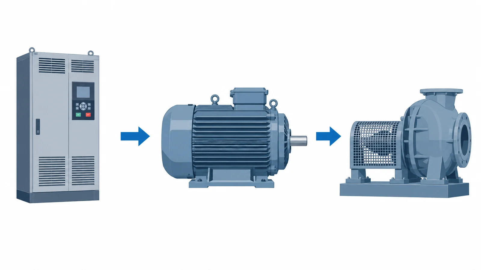
A variable-frequency drive (VFD) controls the electrical frequency supplied to a motor, but frequency is not the same as actual shaft speed. For an induction motor, first calculate synchronous field speed, then account for slip. Use mechanical shaft power—not electrical input power—to calculate shaft torque. A current estimate additionally needs voltage, efficiency and power factor, and is not a substitute for the motor and drive ratings.
This reference concerns three-phase squirrel-cage induction motors in industrial low-voltage applications. The equations provide engineering checks, not permission to change drive settings or a complete protection, thermal or mechanical design. IEC TS 60034-25:2022 is a Technical Specification addressing AC machines supplied by converters, including application and interface considerations; it should not be described as a universal set of VFD settings.
Keep the electrical and mechanical quantities separate
| Symbol | Quantity | Unit and boundary |
|---|---|---|
| f | Motor supply frequency | Hz; use the drive’s output fundamental frequency, not the incoming mains frequency |
| p | Number of motor poles | Integer pole count, not pole pairs |
| nₛ | Synchronous field speed | rpm |
| n | Rotor/shaft speed | rpm, at the stated operating point |
| s | Slip | Dimensionless; multiply by 100 for percent |
| Pout | Mechanical shaft output power | kW, not drive input power |
| T | Shaft torque | N·m |
| VLL | Motor line-to-line voltage | V, for the stated connection and supply model |
| η and PF | Efficiency and power factor | Fractions, at the operating point—not percentages entered as whole numbers |
Do not mix rated full-load data with measured part-load data without explaining the change. A rated shaft-power figure describes a rated operating point; it does not mean the motor produces that power whenever it is running.
1. Calculate synchronous speed from frequency and poles
nₛ = 120f/p
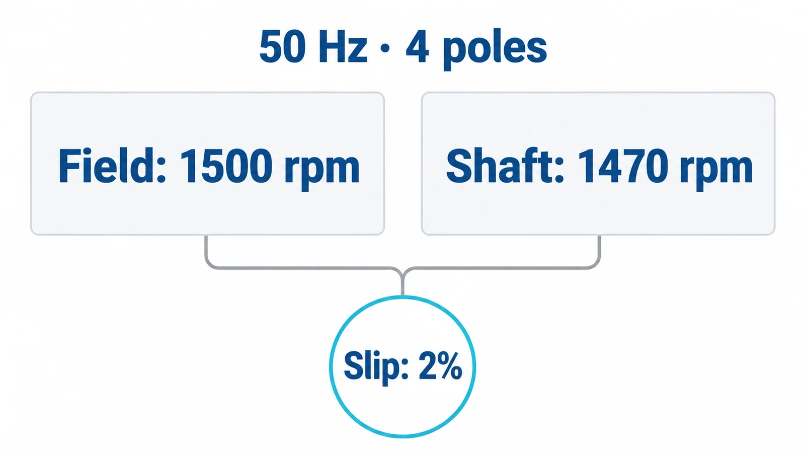
For a four-pole motor at 50 Hz, nₛ = 120 × 50 / 4 = 1,500 rpm. At 25 Hz, the same pole count gives 750 rpm synchronous speed. The latter is not a promise that the shaft runs at 750 rpm.
The US Department of Energy’s motor and drive sourcebook explains the frequency/pole relationship and the difference between induction-motor rotor speed and synchronous speed. Confirm the pole count from reliable motor data; do not equate a rounded catalog speed with an exact pole count in an unfamiliar design.
2. Calculate slip at a defined operating point
For normal motoring operation below synchronous speed:
s = (nₛ − n)/nₛ
Using a hypothetical 50 Hz, four-pole motor running at 1,470 rpm:
s = (1,500 − 1,470)/1,500 = 0.020 = 2.0%
The speed difference is 30 rpm. That percentage belongs to this operating point. Do not carry the same 2% into every VFD frequency or load condition. Load, flux, motor characteristics and the control method affect actual slip; a drive may also apply slip compensation.
At 25 Hz, calculate the 750 rpm field speed first, then obtain the relevant shaft speed from a validated model, suitable measurement or the drive’s properly configured estimate. An estimated speed remains an estimate. For a precision process, determine whether feedback and the control accuracy meet the real requirement.
3. Convert shaft power and speed to torque
Mechanical power is P = Tω, where angular speed ω = 2πn/60. Converting watts to kilowatts gives:
T ≈ 9,550 × Pout/n
Here T is in N·m, Pout in kW and n in rpm. The factor 9,550 is the rounded unit-conversion factor 60,000/(2π).
For an illustrative shaft output of 15 kW at 1,470 rpm:
T ≈ 9,550 × 15/1,470 = 97.4 N·m
This is torque at that assumed point, not starting torque, breakdown torque or permissible continuous torque throughout the speed range. At zero speed, the formula cannot be used by dividing a fixed power by zero; starting and holding duty require the appropriate motor/drive model and limits.
4. Estimate sinusoidal motor current—with the right boundary
For a balanced three-phase sinusoidal operating point:
I ≈ 1,000 × Pout / (√3 × VLL × η × PF)
Assume, solely for a worked example, Pout = 15 kW, VLL = 400 V, η = 0.90 and PF = 0.85:
I ≈ 15,000/(1.732 × 400 × 0.90 × 0.85) = 28.3 A
The estimated motor electrical input is 15/0.90 = 16.7 kW. This is a different quantity from the 15 kW shaft output. DOE’s Determining Electric Motor Load and Efficiency sets out the three-phase input-power relationship and distinguishes input from mechanical output.
This simplified calculation does not determine VFD mains-input current, rectifier harmonics, drive losses or PWM output measurement behavior. Do not insert a PWM voltage reading and an arbitrary “power factor” into it and assume accuracy. Use appropriate measurement methods, operating-point data and the drive’s declared input/output ratings.
For selection, verify rated output current and overload duty against the actual motor and load, including derating conditions. A drive’s kW label alone is insufficient. The VFD selection guide covers that separate application decision. The motor-protection guide covers protection boundaries; calculated operating current is not a complete protective-device setting.
5. Use V/Hz as a screening ratio, not a universal control law
For the illustrative 400 V, 50 Hz motor, the base ratio is 400/50 = 8 V/Hz. A simple constant-ratio calculation at 25 Hz gives 200 V. This is an educational scalar-control comparison, not a commanded setting or a claim about the motor’s complete torque envelope.
Low-frequency voltage drop, control strategy, motor connection and converter limits matter. Vector control is not defined by manually enforcing this simple ratio at every operating point. Above the frequency at which the available voltage reaches its limit, voltage cannot necessarily keep increasing with frequency; reduced flux can limit torque. Obtain the permitted speed/torque envelope rather than assuming constant torque indefinitely.
What a frequency change does not establish
Reducing speed at constant torque reduces mechanical output power because P = Tω. If the illustrative 97.4 N·m were maintained at a hypothetical 735 rpm shaft speed, output would be approximately 7.5 kW. That speed is a separate assumption, not a prediction from “25 Hz.” Lower output power also does not prove adequate cooling: a shaft-driven fan may provide less ventilation at low speed. DOE’s sourcebook specifically flags low-speed cooling as an application concern.
Increasing speed creates a different set of checks: available torque, mechanical limits, driven-machine limits and the validated converter/motor combination. Avoid universal overspeed percentages. An acceptable electrical frequency is not proof that the coupling, bearing system or process can run at that speed.
For an unexpected current or speed change, capture operating frequency, load, actual speed, connection, temperature and alarms before adjusting parameters. If the incoming supply is implicated, the voltage-sag and swell guide addresses the power-quality investigation. Drive setup and hands-on measurements require qualified personnel and the applicable safety procedures, including hazardous stored-energy controls.
The calculation record is complete when every result names its operating point and assumptions, and every intended speed/load point is checked against documented equipment limits. Arithmetic checks plausibility; evidence establishes suitability.