
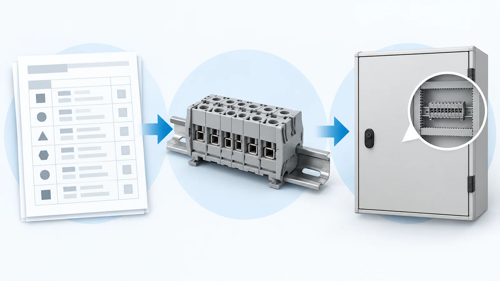
Select a terminal block by circuit function first, then verify conductor acceptance, electrical duty and environmental conditions. Only after those checks should you finalize bridges, protective-earth connections, mounting and panel space. A block that accepts the wire size is not necessarily suitable for the circuit; a suitable individual block is not automatically a suitable complete terminal strip.
This guide follows a new industrial low-voltage panel design using copper conductors. It is IEC-oriented, with a separate approval check for North American projects. It is a specification workflow for qualified designers—not a wiring procedure, product ranking or substitute for the locally applicable panel standard.
1. Build the circuit schedule before the terminal schedule
Record what each circuit must do at the panel boundary: pass current, connect protective earth (PE), distribute a common potential, provide a removable isolation point, accept a fuse or provide a defined test interface. Do not choose a terminal type from its color, width or resemblance to another device.
Feed-through, protective-conductor and fuse terminal blocks have different functions. The official scopes of IEC 60947-7-1:2025, IEC 60947-7-2:2009 and IEC 60947-7-3:2009 distinguish those product areas. A standards reference is a starting point for the evidence request, not proof of compliance for the candidate.
Start with one row per circuit or clearly defined circuit group. A useful schedule includes the drawing reference, function, conductor details, normal duty, insulation conditions, accessories and acceptance evidence. Resolve missing circuit information before procurement rather than hiding it in a generic “terminal block” line item.
2. Translate each input into a specification check
| Design input | Selection consequence | Evidence to retain |
|---|---|---|
| Circuit function | Feed-through, PE, disconnect, fuse or defined test arrangement | Exact function and circuit drawing |
| Conductor material, class and size | Accepted conductor range and preparation; ferrule or lug compatibility where used | Product instructions for the actual combination |
| Current and duty | Rating at the actual ambient and arrangement; accessory current limits | Relevant rating conditions and assembly thermal review |
| Voltage and insulation conditions | Applicable rated voltage, impulse/insulation requirements and separation | Rating basis, installation rules and environmental assumptions |
| Available fault duty and protection | Compatibility with the protected circuit and any specified withstand requirement | Fault/protection assessment and applicable device evidence |
| Bridging or common distribution | Permitted bridge type, positions and current through each segment | Bridge designation, arrangement and its limits |
| Enclosure and environment | Temperature, contamination, condensation and exposure compatibility | Conditions of use and enclosure design |
| Installation and servicing | Rail, end plates, supports, identifiers, tools and access | Completed strip layout and bill of materials |
Do not blend ratings from different approval systems or test conditions. The terminal-block UL/IEC marking guide explains why two printed current values may not be directly comparable.
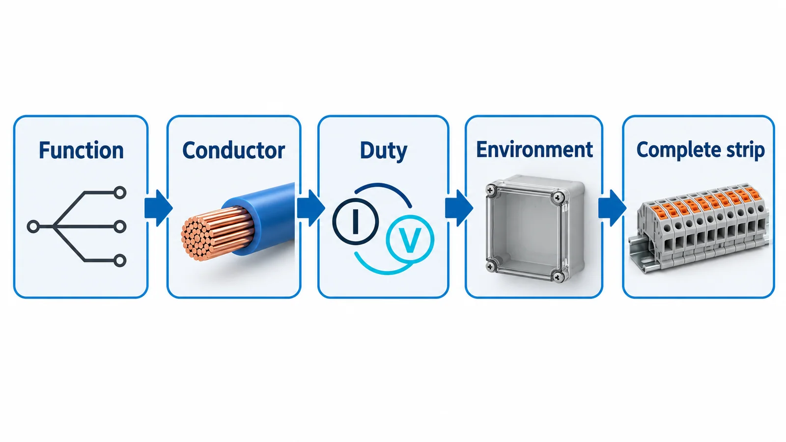
3. Check the conductor combination, not just the largest hole
Specify copper conductor cross-section, conductor class, insulation/temperature conditions and preparation. Confirm whether the block accepts bare flexible conductors, ferrules or another termination method, and whether the declared range changes with preparation. A two-conductor connection needs explicit acceptance; an opening large enough to fit both is not evidence.
The solid-versus-stranded conductor guide addresses this compatibility boundary. Keep the stripping length, tightening requirements where applicable, tools and accepted conductor combination with the exact device designation. Those details must come from the selected product’s instructions, not a generic terminal-size table.
For mixed field wiring, check the smallest expected conductor as well as the largest. A nominally larger block is not automatically more suitable for a small signal wire. Any change after design approval—such as changing a ferrule or connecting two wires—needs a compatibility review.
4. Verify the complete current path and insulation environment
Assess the current in each terminal, bridge and distribution segment. A bridge feeding several branches may carry their combined demand near its supply point. Its current limit can differ from that of the terminal it fits. Multi-level arrangements also require consideration of simultaneous loading and the declared conditions of use.
Voltage selection is not merely matching a nominal system voltage. Identify the relevant insulation-coordination conditions and the approval route for the equipment. IEC 60664-1:2020+AMD1:2025 covers insulation coordination within its stated scope; it does not assign a universal creepage distance to every terminal strip. The pollution-degree selection guide develops the enclosure/environment inputs.
Fault duty needs its own check. A terminal block is generally a connection component, not the protective device that interrupts a fault. For a fused terminal, verify the approved fuse-link arrangement, protection function and relevant limits; do not treat any fuse that fits as acceptable or assume the combination can clear the plant’s available fault current.
5. Treat PE, test and disconnect functions as design decisions
A PE terminal must provide the intended protective-conductor connection through its specified mounting/support arrangement. A green-and-yellow housing does not itself establish that path. Record the rail/support requirements, conductor acceptance and continuity verification for the protective circuit.
A disconnect terminal is likewise not automatically an isolating device suitable for making or breaking the circuit under load. Confirm the declared function and limitations. The symbol on the circuit drawing must match the real device behavior.
For current-transformer (CT) secondary circuits, use an engineered, approved test/shorting arrangement with its documented sequence. Do not substitute a generic removable bridge or ordinary disconnect terminal. The specification must prevent an inappropriate opening of an energized CT secondary; this article does not provide a test-switch operating procedure.
6. Test the workflow with a mixed-function schedule
The following is an illustrative design exercise, not a finished bill of materials or a set of equipment ratings:
| Circuit group | Required function | Decision that cannot be skipped |
|---|---|---|
| Control-power branches | Feed-through with an approved distribution bridge where needed | Combined bridge current, branch protection and identification |
| Instrument signal pair | Signal feed-through or an explicitly specified disconnect/test function | Accepted small conductor and exact circuit continuity behavior |
| Field protective conductors | PE terminals on the specified support system | Verified protective path, mounting and continuity |
| Protected auxiliary branch | Fuse-terminal arrangement if the design calls for it | Correct fuse function, approved link and fault-duty compatibility |
This exercise exposes why “one terminal type for the whole panel” is often an incomplete specification. Standardization is useful only after every required function and condition is satisfied.
7. Freeze the strip only when the evidence is complete
Include end plates, end stops, partitioning, bridge accessories, markers and service access in the final layout. Use the DIN-rail terminal-space guide for the layout task; the body width alone is not the complete space allowance.
For a US-bound industrial panel, separately verify the applicable approval route and component conditions of acceptability. The US terminal-block compliance guide addresses that boundary. Component approval is not a blanket approval of the assembled panel.
Selection is complete when each schedule row names the exact device and accessories, records the applicable rating conditions and conductor preparation, and points to the evidence used. Installation, inspection and commissioning then follow the approved drawings, exact instructions and qualified-person safety procedures. If a row still depends on an assumed rating, improvised bridge or unspecified PE path, the design is not ready to release.