
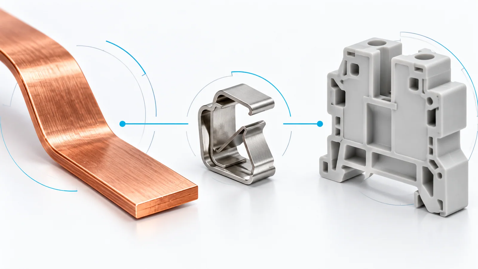
A terminal block is a connection system, not a single material. Its conducting parts carry current, its clamping mechanism maintains contact, its surface finish affects the interface, and its housing provides insulation and mechanical support. Durability and electrical loss depend on these parts working together under the actual conductor, load and environment—not on a label such as “copper” or “high-temperature plastic” alone.
For industrial low-voltage copper-conductor blocks, start with the applicable product evidence. IEC 60947-7-1:2025 covers terminal blocks with screw-type or screwless clamping units within its stated scope. Its existence does not establish that a particular block complies, accepts a particular conductor, or will perform indefinitely in a harsh enclosure. This guide explains the material mechanisms; it does not rank brands or assign service life.
Separate the four material roles
| Part or interface | What its material contributes | What to verify on the complete block |
|---|---|---|
| Current-carrying bar and contacts | Conductivity, geometry-dependent resistance and compatibility with the connected conductor | Declared current and conductor range, temperature-rise evidence and intended operating conditions |
| Clamp, screw or spring | Contact-force generation and retention through the specified duty | Accepted conductor types, preparation instructions, mechanical retention and applicable endurance evidence |
| Contact surface or plating | The surface presented to the conductor; corrosion and wear behavior at that interface | Finish identification, environmental suitability and evidence for the assembled connection |
| Insulating housing | Electrical separation, positioning and mechanical support | Insulation ratings, material tracking data where relevant, temperature conditions and chemical/environmental compatibility |
These are functional roles, not a universal bill of materials. A spring need not be the main current path; some designs separate the force-producing part from the conducting bar. Do not infer an unfamiliar block’s construction from its outside appearance.
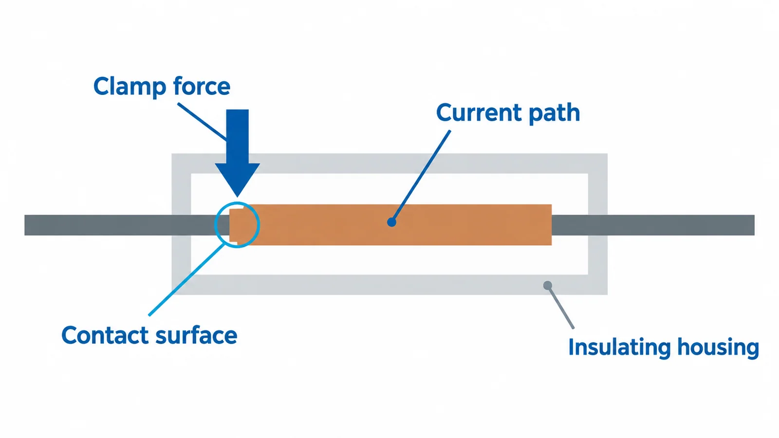
Bulk conductivity is not the whole connection resistance
For an ideal uniform conductor, resistance follows R = ρL/A, where ρ is resistivity, L is path length and A is cross-sectional area. That model explains why both metal and geometry matter. A short, wide conducting path and a narrow, long one cannot be compared by alloy name alone.
A real terminal also contains contact interfaces. Their resistance depends on the actual metal-to-metal contact, surface condition and maintained force. A highly conductive bar cannot compensate for a poorly formed interface, an unsupported wire preparation or contamination.
NASA’s NESC connector assessment identifies contamination, corrosion, inadequate retention and installation workmanship among connector problem categories. It concerns spacecraft connectors, not DIN-rail terminal certification; its relevance here is the general lesson that the interface and mechanical system deserve attention alongside the base metal.
Check the conductor first. The approved combination may distinguish solid, stranded and flexible conductors, ferrules, conductor size and the number of conductors per clamping unit. The solid-versus-stranded terminal connection guide explains why a nominal cross-section alone is an incomplete compatibility statement.
Calculate the heat consequence without inventing an efficiency claim
The resistive loss in a defined connection path is P = I²R. Use current in amperes, resistance in ohms and power in watts. For this simple comparison, assume steady DC current and a fixed measured path resistance; real resistance can change with temperature and condition.
Consider two hypothetical connections carrying 20 A:
| Assumed path resistance | Calculation | Local resistive loss |
|---|---|---|
| 0.5 mΩ = 0.0005 Ω | 20² × 0.0005 | 0.20 W |
| 2.0 mΩ = 0.0020 Ω | 20² × 0.0020 | 0.80 W |
The second path dissipates four times the power at the same current. These are illustrative values, not measured terminal-block results or acceptance limits. Neither result establishes housing temperature: that also depends on heat transfer, adjacent loaded terminals, conductor heat flow, enclosure conditions and the product’s construction.
The useful conclusion is local: resistance control matters at the connection. A claim about whole-panel efficiency or annual energy savings would additionally require actual resistance, load history, operating hours and a defined system boundary. A material substitution alone supplies none of those inputs.
Contact force and finish must survive the intended duty
A screw or spring connection must retain the conductor and form the intended interface. Incorrect tightening, unsupported ferrules, damaged strands or mismatched wire sizes can undermine that system even when the materials are appropriate. More torque is not a remedy: use the exact device instructions, and do not improvise a retightening interval.
Surface finish is likewise a design choice rather than a quality ranking. Plating may serve a corrosion or interface function, but its suitability depends on the base material, finish system, contact mechanics and exposure. “Plated” does not mean immune to corrosion, and visible color does not prove composition or thickness. Compare documented constructions and relevant test evidence, not appearance.
For vibration or temperature cycling, request evidence for the specified connection and mounting arrangement. Do not transplant a result from another terminal family merely because both use the same metal or clamping label.
Housing properties answer different questions
Tracking resistance, thermal suitability and resistance to chemicals are not interchangeable properties.
IEC 60112:2025 defines comparative tracking index (CTI) and proof tracking index (PTI) test methods for solid insulating materials. A tracking-test result is not a universal operating-voltage rating or a service-life prediction. IEC 60664-1:2020+AMD1:2025 addresses insulation coordination for equipment within its low-voltage scope; the installed design must also account for its electrical and environmental conditions.
Ask for the actual material grade and product conditions when heat, condensation, conductive dust, cleaners or outdoor exposure are material risks. A polymer family name alone is insufficient. A flammability classification also does not establish continuous thermal endurance or suitability for every chemical.
Use the terminal-block pollution-degree guide to separate the surrounding environment from the block’s declared insulation conditions. The housing cannot compensate for an enclosure design that exposes it to conditions outside its intended use.
Compare evidence, then materials
A defensible comparison record identifies the circuit duty, accepted conductor, clamping method, current path and finish, housing/environment limits, relevant product tests and installation instructions. Use the UL/IEC marking guide to distinguish standard references from ratings or approval evidence.
If an existing block shows discoloration, cracking, corrosion or unstable continuity, investigate the connection and operating conditions before selecting a “better material.” Replacement is a separate controlled task; the terminal-block replacement checklist covers compatibility and restoration checks. Hands-on inspection or repair requires qualified personnel, isolation, verification of absence of voltage and the site’s safety procedure. Material knowledge helps frame the investigation; it does not make an energized connection safe to touch.