
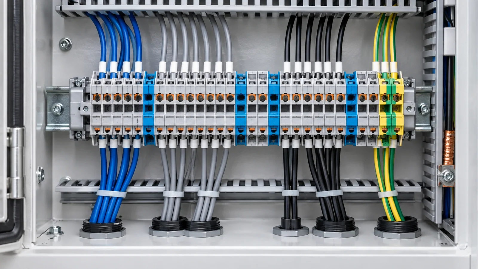
Select a terminal block for the pollution degree of the insulation’s local microenvironment, not simply for the building’s general description. That choice affects the required creepage-distance assessment. It is only one part of insulation coordination: working voltage, insulation material, clearance, impulse withstand, and the product standard also matter. There is no safe universal rule such as “multiply the creepage by two for pollution degree 3.” Use the applicable IEC tables and the terminal block’s documented rating conditions for the actual assembly.
This guide addresses low-voltage industrial terminal blocks for copper conductors in IEC-based equipment. IEC 60947-7-1:2025 covers specified screw and screwless terminal blocks intended for industrial or similar use at circuit voltages not exceeding 1,000 V AC or 1,500 V DC, within its other scope limits. A terminal sold to a different standard, a special-function block, a field connector or a medium-voltage termination needs its own product requirements.
Pollution degree is an exposure classification
In insulation coordination, pollution degree characterizes contamination near the insulating surface and whether it can become conductive. The designer must consider what the terminal actually experiences: dust, humidity, condensation, process residue, maintenance exposure, and the protection provided by the enclosure. A nominally clean control room does not settle conditions inside a cabinet where condensation forms. Conversely, an enclosure may create a more protected local microenvironment than the surrounding industrial space—but only if the enclosure design and operating conditions support that claim.
IEC 60664-1:2020 with Amendment 1:2025 is the horizontal insulation-coordination framework for equipment connected to low-voltage supply systems, within its scope. It provides methods for determining creepage and clearance; the relevant terminal-block product and assembly standards still control their own applications. Pollution degree is not an IP rating: ingress protection says something different from whether contaminants or moisture create a conductive surface path at a particular insulator.
| Local condition to assess | Why it matters | Evidence to request |
|---|---|---|
| Dry, controlled enclosure with no expected condensation | A lower pollution classification may be supportable | Enclosure design, climate control, operating range and installation conditions |
| Conductive dust, wet deposits or recurrent condensation | Surface tracking and leakage risk may increase | Process contamination, humidity/temperature profile, inspection history |
| Airflow, cable entries or door-opening pattern | Cabinet interior may not be uniform | Layout and maintenance regime |
| Terminal position and adjacent devices | Actual creepage path may differ from a catalog sketch | Assembly drawing and rated accessory configuration |
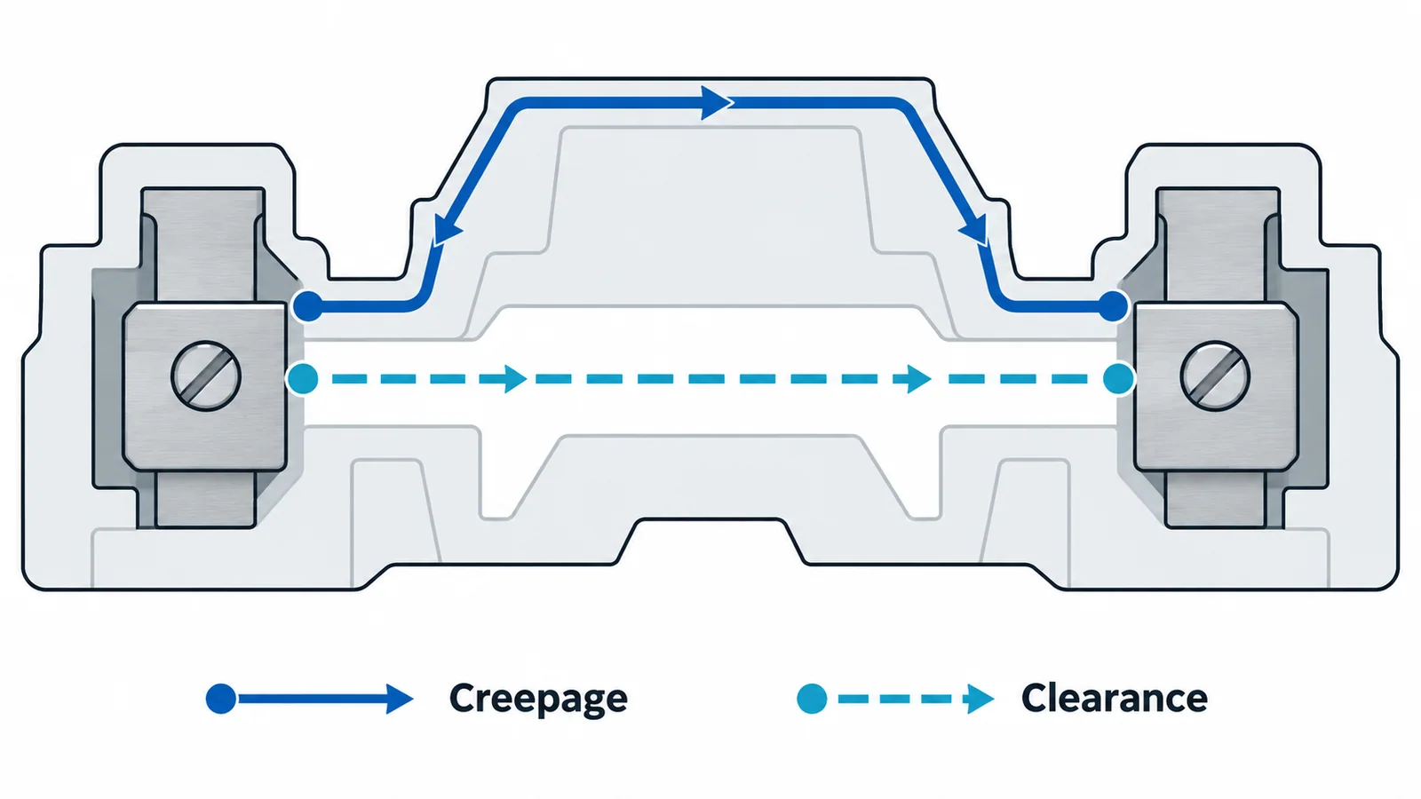
Do not confuse creepage with clearance
Creepage distance follows the surface of solid insulation between conductive parts. It is sensitive to the surface material and contamination conditions. Clearance is the shortest distance through air and is associated with impulse and overvoltage withstand, including installation altitude where relevant. A barrier or separator may lengthen one path without automatically proving the other path adequate.
The barrier terminal block installation guide explains how a barrier changes the physical arrangement without becoming a blanket insulation approval. Actual distances have to be evaluated for the chosen block, end plates, bridges, adjacent devices and mounting configuration. Do not measure only the empty block body and ignore installed accessories.
A practical selection sequence
- Define the circuit duty. Record AC or DC, maximum working voltage between relevant conductors and to earth, nominal system, expected overvoltages and the insulation function being provided. A printed “voltage rating” without its test conditions is not enough.
- Classify the local environment. Document how the selected pollution degree follows from the inside of the enclosure, including credible condensation, contamination and maintenance conditions. If the enclosure is relied upon to create a cleaner microenvironment, identify how that assumption is maintained.
- Identify the product and assembly rules. Check the applicable edition of IEC 60947-7-1 and IEC 60947-1:2020 where the product standard invokes its general rules. Also check the enclosing equipment’s own requirements. A component rating does not certify the completed panel.
- Verify insulation dimensions and material assumptions. Obtain the terminal block’s declared insulation data, creepage/clearance details or conformity documentation for the selected voltage, pollution degree and configuration. Material tracking behavior matters to creepage assessment; do not substitute a color or plastic name for a documented material group.
- Check the installed configuration. Review links, markers, end plates, protective covers, mixed-potential adjacency, wiring bend space and any exposed metal parts. Ensure the manufacturer’s permissible accessories and spacing are followed without generalizing one model’s geometry to every block.
- Record the selection basis. The drawing or bill of materials should capture the assumed environment, voltage, terminal family, accessory set and relevant standard edition. This makes future substitutions reviewable.
There is no single formula using only voltage and pollution degree that yields a valid terminal-block choice. The IEC insulation-coordination framework supplies the relevant method, while the product standard and equipment documentation determine what is actually verified. The official public catalog does not publish all numerical tables; this article therefore does not invent millimetre values or present a fabricated example.
Selection worksheet
| Required input | Project entry | Acceptance evidence |
|---|---|---|
| Circuit working voltage and AC/DC duty | Project electrical schedule | Rating matches the circuit and insulation function |
| Local pollution degree | Documented cabinet microenvironment | Assumption remains valid in service |
| Impulse/overvoltage environment | Equipment insulation-coordination study | Clearance and withstand documented |
| Insulating material and surface path | Product technical documentation | Creepage basis applicable to actual configuration |
| Terminal-block standard and edition | Product conformity documentation | Product falls within stated scope |
| Accessories and adjacency | Assembly drawing | Installed path and protection verified |
If any row is unknown, the appropriate result is more design evidence, not a guessed creepage adjustment. For label and standard interpretation, see the terminal-block markings guide.