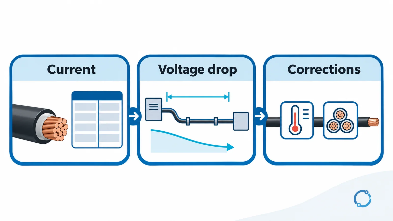
Short answer: Choose wire size in three steps. First, use the load current and the applicable ampacity table to establish a minimum AWG. Second, calculate voltage drop over the actual one-way distance and enlarge the conductor if the result exceeds the design target. Third, apply the temperature, grouping, termination and installation corrections that the code and equipment require.
The important conclusion comes before the table: a conductor that passes the ampacity check can still be too small for a long run. In many long-distance circuits, voltage drop, not heat, forces the final size increase. A good wire size guide therefore treats ampacity and voltage drop as two different questions.
This method is for low-voltage branch circuits and feeders where the conductor is selected from an adopted code or approved engineering basis. It does not replace a load calculation, a short-circuit study, an electrician’s installation review or the local authority’s interpretation.
The breaker rating is not a substitute for the load calculation. A breaker protects the circuit within its own rating and listing, but the connected load, continuous-duty portion, starting current and future operating plan determine the current that the conductor must carry. A 30 A breaker does not prove that a circuit will draw 30 A, and a 20 A load does not become a 20 A conductor selection until the applicable factors and installation conditions are included.
Step 1: set the current-based lower bound
Start with the current that the circuit is expected to carry, not with the breaker handle rating alone. The load calculation establishes the design current. For a continuous load, many branch-circuit and feeder calculations apply a 125 percent factor to the continuous portion before selecting conductors and overcurrent protection. The exact rule, its exceptions and the adopted edition must be checked in NEC 210.19 and 215.2 or the locally applicable code.
For a simple screening example, a 20 A continuous load contributes 25 A to that part of the calculation:
20 A x 1.25 = 25 A
That does not mean every 20 A circuit needs a conductor rated exactly 25 A. It means the continuous-load factor must be included before comparing the result with the ampacity table. Noncontinuous portions, special loads and listed 100 percent-rated equipment require their own treatment.
Use the AWG wire size chart to find the table value. In the 75 C reference column of NEC Table 310.16, 12 AWG copper is listed at 25 A, 10 AWG at 35 A and 8 AWG at 50 A. Those values assume not more than three current-carrying conductors, a 30 C ambient and the other conditions of the table. They are a starting point, not the final installed ampacity.
The lower-bound answer at this stage is the smallest conductor whose corrected ampacity is at least the calculated current. If the conductor will be installed in a high-temperature area, bundled with other current-carrying conductors or terminated in equipment with a lower temperature rating, the correction can eliminate the apparent margin. Do not lock in the first size that passes the uncorrected table.
The ampacity check also has a protection dimension. The overcurrent device must protect the conductor under the adopted rules, and the conductor must be able to carry the load after adjustment and correction. Those are related checks, not the same check. The circuit-breaker and feeder cable-sizing workflow covers the broader set of coordination gates; this guide deliberately stays with the current-to-distance selection method.
Step 2: check voltage drop over the one-way distance
Once the current-based minimum is known, test whether the conductor can deliver acceptable voltage at the load. For a single-phase, two-wire circuit, a common approximate formula is:
VD = 2 x K x I x L / CM
Where:
VDis the approximate voltage drop in volts.Kis a calculation constant: 12.9 for copper and 21.2 for aluminum in the conventional teaching form used here.Iis the load current in amperes.Lis the one-way circuit length in feet, not the round-trip length.CMis the conductor area in circular mils.
The factor of two accounts for the outgoing and return conductors in a single-phase two-wire circuit. If the distance is entered as a round trip and the factor of two is also applied, the result is twice as large as intended. This is one of the most common calculation errors.
For a balanced three-phase circuit, the corresponding approximate relationship uses the square root of three rather than two:
VD = sqrt(3) x K x I x L / CM
That form assumes a balanced load and a reasonable approximation of the conductor’s effective resistance. It is not a substitute for a full impedance calculation when reactance, power factor, harmonics, parallel conductors or unusual cable geometry matter.
Metric equivalent
The same idea can be written with conductor resistance per unit length:
VD = 2 x I x R x L
For a single-phase circuit, R is the conductor resistance in ohms per kilometre and L is the one-way length in kilometres. The result is in volts when current is in amperes. For three-phase, use sqrt(3) in place of the factor of two. Use the resistance value for the actual conductor material, temperature and construction; a nominal room-temperature value is only a starting point.
The formula is a screening calculation, not a code limit. The commonly cited 3 percent and 5 percent voltage-drop figures appear in NEC Informational Notes as guidance. They are not universal mandatory limits for every circuit. Confirm the adopted code, the equipment instructions, the project specification and the performance requirement of the load before selecting a target.
Worked Example A: voltage drop forces a larger conductor
Assume a single-phase 120 V copper branch circuit carries 20 A over a one-way distance of 30 m, or 98.4 ft. The design target is 3 percent voltage drop, which is 3.6 V at 120 V.
The current-based screening points to 12 AWG copper. Its 75 C reference ampacity is 25 A, so it is a plausible starting point for the current. Now calculate the voltage drop using the Table 8 circular-mil values from the AWG wire size chart.
12 AWG
CM = 6,530
VD = 2 x 12.9 x 20 A x 98.4 ft / 6,530
VD = 7.78 V
7.78 V / 120 V = 6.5%
The approximate voltage drop is 7.78 V, or 6.5 percent. That is above the assumed 3 percent target, so the 12 AWG conductor fails the voltage-drop check even though its ampacity is above the load current.
10 AWG
CM = 10,380
VD = 2 x 12.9 x 20 A x 98.4 ft / 10,380
VD = 4.89 V
4.89 V / 120 V = 4.1%
The 10 AWG result is better, but it is still above the assumed 3 percent target. It would not satisfy that particular design goal.
8 AWG
CM = 16,510
VD = 2 x 12.9 x 20 A x 98.4 ft / 16,510
VD = 3.08 V
3.08 V / 120 V = 2.6%
The 8 AWG result is approximately 3.08 V, or 2.6 percent. It satisfies the assumed 3 percent target and therefore controls the selection for this example. The example is hypothetical teaching data, not a field measurement or a universal recommendation.
The lesson is not that every 20 A circuit needs 8 AWG. The lesson is that a long run can turn a voltage-drop check into the controlling constraint. A shorter run, a lower current or a different design target could leave the smaller ampacity-based size in place.
Worked Example B: a passing voltage-drop check leaves the size unchanged
Assume a 240 V single-phase copper feeder has an already calculated load current of 60 A, a one-way distance of 15 m, or 49.2 ft, and a 3 percent voltage-drop target. Treat the 60 A as the load current after the applicable load calculation, not as a 60 A continuous load that needs another 125 percent step.
The 75 C reference ampacity of 6 AWG copper is 65 A. The conductor is therefore a plausible current-based candidate. Its Table 8 circular-mil area is 26,240 CM.
VD = 2 x 12.9 x 60 A x 49.2 ft / 26,240
VD = 2.90 V
2.90 V / 240 V = 1.2%
The approximate drop is 2.90 V, or 1.2 percent, which is well below the assumed 3 percent target. In this example, 6 AWG remains the size after the voltage-drop check; there is no voltage-drop reason to enlarge it.
This second example matters because a selection guide should not teach “always go larger.” Enlarging a conductor has real costs, termination limits, bending-space consequences and possible fault-current or voltage-rise effects. The correct size is the one that satisfies the applicable ampacity, voltage-drop and installation checks, not the largest size that physically fits.
Step 3: apply the corrections before the final answer
The three-step method is not complete when the arithmetic produces a size. The final size must survive the conditions that the table assumptions did not include.
Ambient temperature
The 75 C ampacity column is based on a 30 C ambient. A hotter location can require an ambient correction. The conductor insulation, the equipment rating and the actual maximum ambient all matter. Do not apply an insulation correction while ignoring the lower temperature rating of the terminals.
More than three current-carrying conductors
Bundling or raceway fill can require an adjustment for the number of current-carrying conductors. The exact count and the adopted code method control. A bundled cable that looks adequately sized in open air may not retain the same usable ampacity inside a crowded raceway.
Termination temperature
The breaker, load equipment and terminal block may be marked for 60 C, 75 C or another temperature. The lowest controlling rating can limit the ampacity used at the termination. A conductor with 90 C insulation is not automatically usable at its 90 C table value.
Conduit fill and installation method
Conduit fill is not just a pulling convenience. It affects heat dissipation and the permitted installation method. Bend radius, jam ratio, cable jacket, support, moisture, sunlight and physical protection can also eliminate a conductor that passed the electrical calculation.
Protective-device and fault checks
The conductor must be coordinated with the overcurrent device and the available fault current. The equipment grounding conductor, short-circuit withstand, voltage rise during a fault and the interrupting rating of the protective device remain separate requirements. A voltage-drop calculation cannot substitute for them.
For a single-case illustration, the 100 A breaker wire-size analysis shows why the same breaker rating can produce different copper and aluminum answers when terminal temperature and table conditions change. Use that page as a case entry, not as a replacement for this three-step method.
A practical selection record
A defensible conductor selection record should contain:
- the calculated load current and the continuous/noncontinuous breakdown;
- the adopted code edition and the applicable ampacity table;
- conductor material, insulation and termination temperature;
- ambient-temperature and conductor-count corrections;
- the one-way distance and the selected voltage-drop target;
- the resistance or circular-mil input and the formula used;
- the voltage-drop result before and after any size change;
- the protective-device, fault-current and equipment-grounding checks;
- the installation method, conduit fill, bending and termination limits;
- the manufacturer instructions for the exact equipment.
The record should show why the next smaller size fails, not only why the selected size passes. That is the difference between a selection and a guess.
Four common mistakes
Selecting from current alone
A conductor can pass the ampacity table and still produce excessive voltage drop at the load. Current sets a lower bound; distance and the design voltage target can raise the final size.
Using the round-trip distance in a formula that already includes the return path
The formula in this guide uses one-way length and a factor of two. Entering the round-trip distance as L doubles the result. Write the distance definition beside the number before calculating.
Using a copper K value for aluminum
The approximate constants are different: 12.9 for copper and 21.2 for aluminum in the teaching form used here. Aluminum also needs terminations and connectors identified for aluminum. A material substitution is not just a change in a formula constant.
Stopping after one calculation
The first answer is a candidate, not a completed design. Apply ambient correction, conductor grouping, termination limits, conduit fill, fault protection, voltage drop and equipment instructions. If any controlling condition changes the usable ampacity, repeat the selection.
FAQ
What is the first step in choosing wire size?
Establish the calculated load current, including the applicable continuous-load treatment, and compare it with the corrected ampacity of candidate conductors. That gives the current-based minimum before voltage drop is checked.
Why does voltage drop sometimes control wire size?
Voltage drop increases with current and one-way conductor length and decreases as conductor area increases. On a long run, the voltage loss can exceed the design target even when the conductor’s ampacity is adequate.
Should I use 3 percent or 5 percent voltage drop?
Those values are familiar Informational Note guidance, not universal mandatory limits. Select the target from the adopted code, equipment requirements and project criteria, then document the basis.
Does a larger conductor always improve the installation?
No. A larger conductor can improve voltage drop but may create termination, bending, support, fault-current or equipment-fit issues. The correct result is the smallest compliant and workable size that satisfies the complete design basis.
Can I use the same AWG in aluminum as in copper?
No. Aluminum generally has lower same-size ampacity, and the terminations must be identified for aluminum. The final size must come from the adopted table and the actual connector and equipment requirements.