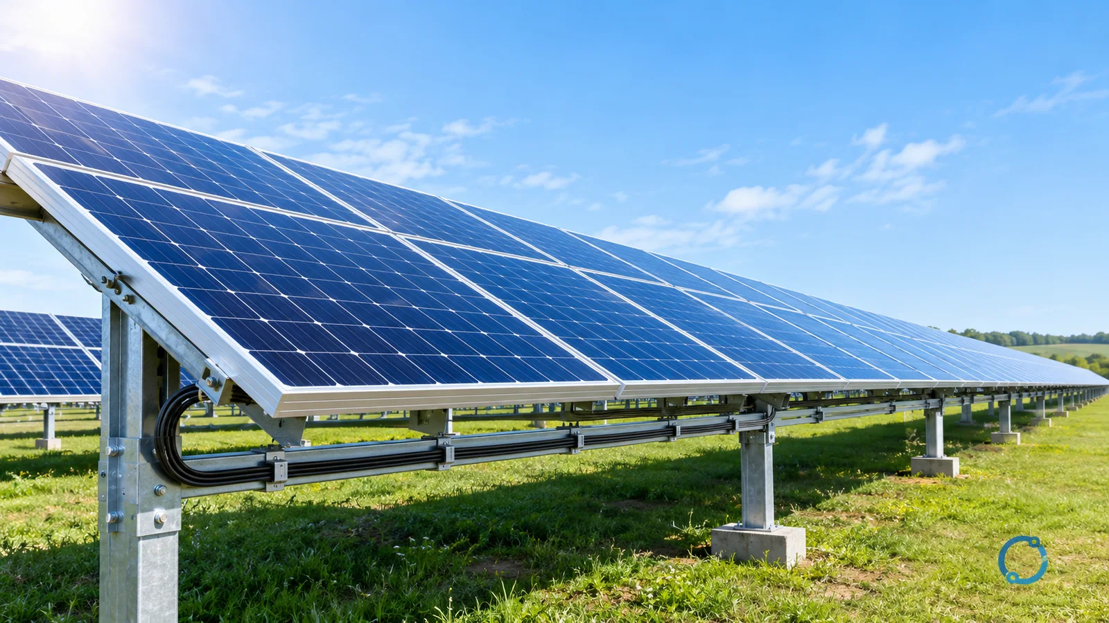
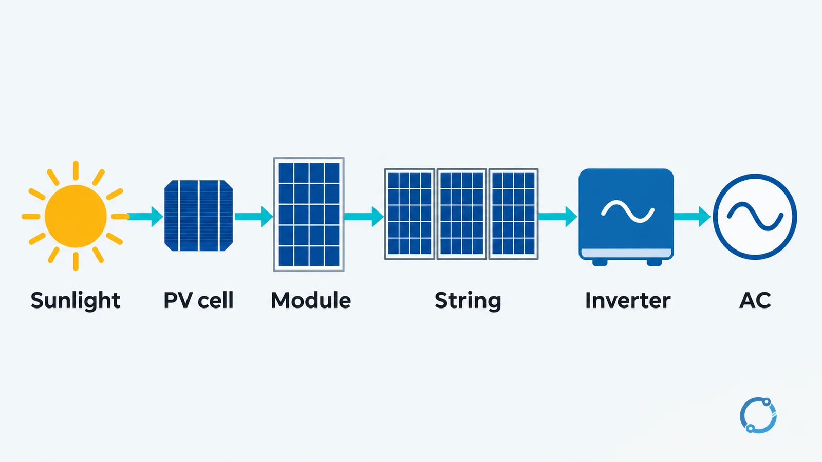
Short answer: Sunlight transfers energy to electrons in a photovoltaic cell. The cell’s semiconductor structure separates those charges and produces direct current. Cells are connected into a module, modules are connected into strings, and an inverter converts the direct current into alternating current for a grid or an off-grid electrical system.
The complete chain is:
photons -> photovoltaic effect -> DC electricity -> cells and modules -> strings -> inverter -> AC output
Each stage has a different job. Keeping those jobs separate makes it easier to understand why a solar panel has a rated voltage and current, why shading can affect more than one panel, and why an inverter is needed even though the solar panel already produces electricity.
Step 1: light reaches a semiconductor
A solar panel starts with the photovoltaic effect: light can transfer enough energy to a material to release charge carriers and create a voltage between two regions. In a common crystalline-silicon cell, the important structure is a junction between p-type and n-type semiconductor material.
The names describe the dominant charge-carrier behavior rather than two separate metal plates. At the junction, an internal electric field forms. When light is absorbed, electron-hole pairs can be separated by that field. Electrons move toward one side of the structure and holes move toward the other, creating a potential difference and a current path when the cell is connected to an external circuit.
The practical point is simple: the cell does not store a tank of electricity that drains like a battery. It converts incoming light into separated charge and maintains an electrical output while it is illuminated and connected to a load. The energy source is the light, and the semiconductor is the conversion medium.
Not every photon produces the same result. A photon must have enough energy to participate in the absorption process, and excess energy can become heat rather than useful electrical output. That is one reason a real module does not convert all incoming sunlight into electricity, and why module temperature matters.
Step 2: from a cell to a solar panel
A single silicon cell produces a limited voltage and current. Manufacturers connect cells in series and parallel arrangements inside a module to obtain a useful voltage and current combination.
- Series connection adds voltage while the current through each series element is constrained by the same current path.
- Parallel connection adds current while the voltage across the parallel branches remains nominally common.
A module datasheet condenses the electrical behavior into four useful parameters:
| Parameter | Plain-language meaning |
|---|---|
Voc |
Open-circuit voltage: the voltage with no external load connected. |
Isc |
Short-circuit current: the current with the output terminals shorted under the stated test conditions. |
Vmp |
Voltage at the maximum-power point on the illuminated current-voltage curve. |
Imp |
Current at that maximum-power point. |
Voc is not the normal operating voltage of a loaded module, and Isc is not the current a designer should expect at every operating point. The maximum-power values, Vmp and Imp, describe the point where the module delivers its highest power under the specified test condition. Actual operating values change with irradiance, temperature and the rest of the system.
The module also protects and packages the cells. A typical laminated construction includes:
- a transparent front glass;
- an encapsulant that seals and bonds the layers;
- the interconnected solar cells;
- a backsheet or rear structural layer;
- a frame and edge seal where the product design requires them;
- a junction box and output cables.
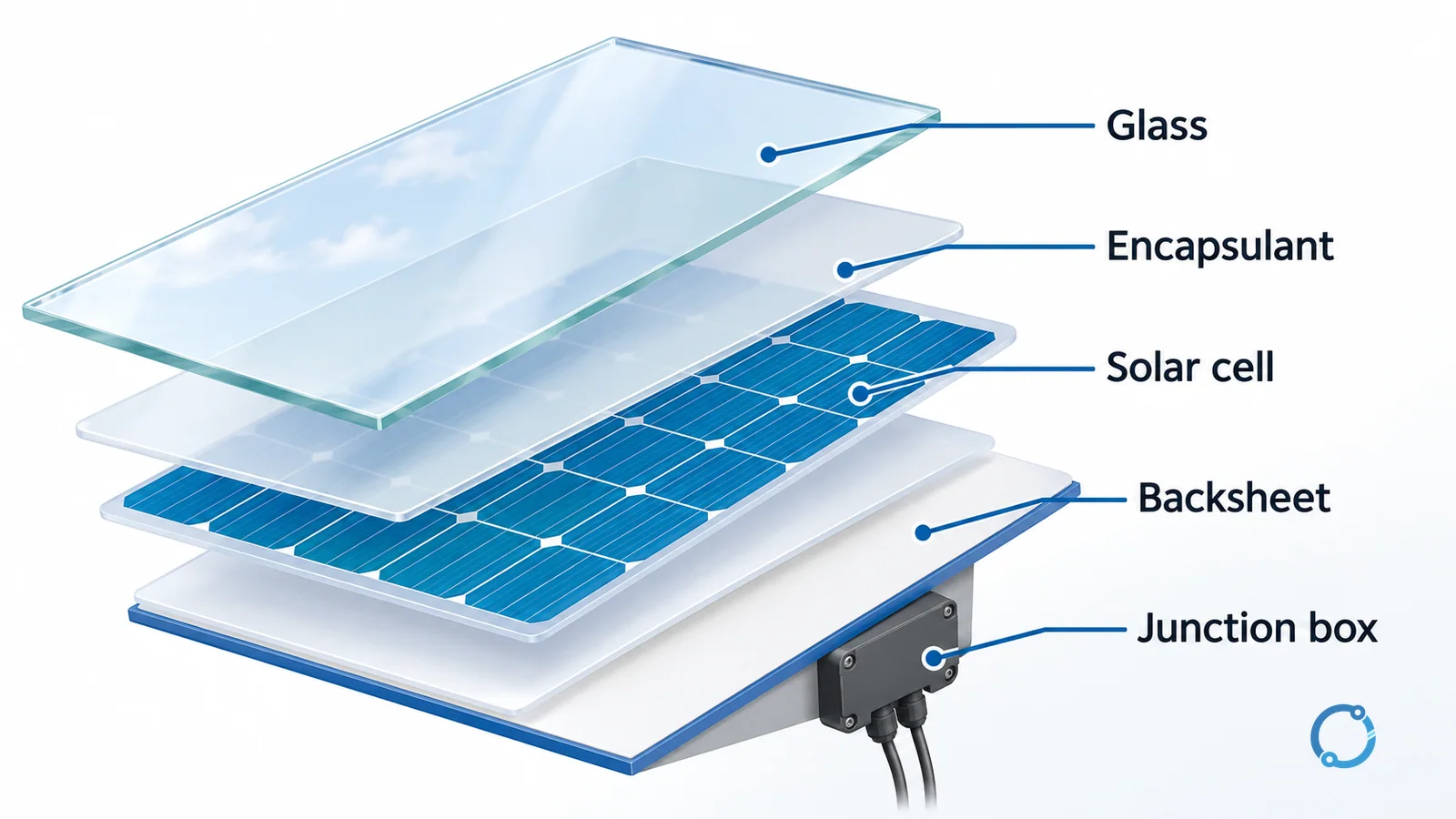
The exact layer order, materials and construction vary by product. The diagram is conceptual; the manufacturer’s construction drawing and datasheet control the actual design.
Step 3: from modules to strings and the DC side
A photovoltaic module is a DC source. Installers and system designers connect modules in series to build a string voltage and may connect strings in parallel at a combiner or inverter input. The array is the complete collection of modules and their electrical arrangement.
The string voltage is not simply a label to ignore. Module open-circuit voltage rises as cell temperature falls, so the coldest expected condition can be a limiting case for equipment voltage ratings. The operating voltage and current also vary with irradiance, temperature and the inverter’s control of the array. System design therefore uses the module’s temperature coefficients and the equipment’s voltage window, not only the standard test-condition numbers.
The DC side has conductors, connectors, disconnects, combiners, fuses or other protective devices, and an inverter input. Voltage drop is still a physical issue on this side. A long DC run can lose power and shift the voltage available at the inverter, just as a long AC feeder can lose voltage at a load. The voltage-drop calculation guide explains the conductor-length relationship; the solar designer must apply it to the actual DC circuit and its operating voltage.
Higher string voltage can reduce current for the same power and may reduce conductor losses for a given run, but it also changes equipment voltage ratings, insulation requirements, connector selection and safe-work boundaries. “Higher voltage is better” is not a universal rule. The system voltage must remain within the ratings of every connected component.
Step 4: the inverter changes DC to AC
The inverter is the power-electronics interface between the DC array and the AC destination. It switches and controls the DC input so that the output approximates the required AC voltage and frequency. A grid-tied inverter synchronizes with the grid and normally stops exporting when the grid is unavailable, subject to the equipment’s protection functions. An off-grid inverter may form its own AC system and work with a battery or another energy source.
The inverter is not a simple passive adapter. It controls the operating point of the array, converts power, regulates output, monitors grid or system conditions and protects itself and the circuit within its design. The exact functions depend on the inverter type, its listing, its settings and the system architecture.
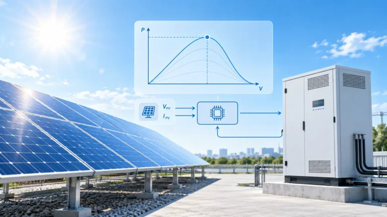
Maximum power point tracking, or MPPT, sits inside this control layer. A photovoltaic array’s current-voltage curve has a maximum-power point, and that point moves as irradiance and temperature change. An MPPT controller adjusts the operating point to seek that maximum rather than holding the array at one fixed voltage. The MPPT algorithm overview explains the control methods; for this principle article, the important point is that MPPT manages the array operating point before the inverter delivers AC power.
Step 5: where efficiency and losses go
Module efficiency compares electrical output with the solar energy incident on the module area under defined test conditions. It is not the same as system efficiency, because the complete system also has inverter conversion loss, wiring loss, mismatch, soiling, shading, temperature effects and availability losses.
Many mainstream single-junction silicon modules are in the low-20 percent efficiency range, but that is a qualitative orientation rather than a universal product value. Use the actual module datasheet for the tested efficiency, temperature coefficients, power tolerance and operating limits. A higher-efficiency module can reduce the area needed for a given output, but it does not automatically make the complete system more reliable or more economical.
Temperature
Photovoltaic modules generally produce less power at higher cell temperatures for the same irradiance. The datasheet expresses this through a temperature coefficient, usually as a percentage change per degree Celsius for power, voltage and current. The coefficient is product-specific; this article does not invent one. Good ventilation and mounting design can affect cell temperature, but the exact thermal behavior depends on the installation and environment.
Shading and mismatch
Shading is not a simple percentage reduction applied evenly across an array. A shaded cell or group of cells can limit the current through a series string and create a local operating problem. Bypass diodes in the module can provide a current path around affected cell groups, but they do not make the shaded area generate full power. Partial shading can therefore have a disproportionate effect on string output.
Module mismatch has a similar lesson: series-connected devices share a current path, so a weak element can constrain the stronger elements. The system designer uses string layout, bypass behavior, inverter input limits and, where appropriate, module-level electronics to manage this. The principle is that the array is an electrical network, not a collection of independent panels.
Orientation and irradiance
The amount of light reaching the module depends on the sun’s position, the module tilt and orientation, atmospheric conditions and nearby obstructions. A surface facing away from the strongest incident light receives less irradiance. The effect changes through the day and year, so a single “best angle” cannot be applied without the site’s latitude, load profile and mounting geometry.
Step 6: what happens at night and in cloudy weather
At night, a photovoltaic module has no light input and therefore no photovoltaic generation. The array does not become a generator simply because it remains connected. A grid-tied system can continue to receive power from the grid for loads, subject to the inverter and system design. An off-grid system relies on batteries or another source to carry the load through the dark period.
In cloudy weather, the module still receives diffuse and scattered light, so it may generate some power. The output is generally lower and more variable than under clear-sky conditions. The inverter may continue to operate if the DC input remains within its operating window, but the system cannot be assumed to deliver its rated output.
This is why energy storage and backup planning are separate from the question of how a panel converts light. The panel is a power source only while it is illuminated and electrically connected to an operating conversion path. The explanation of kW and kWh helps separate instantaneous power from energy over time, and the guide to how electricity is generated places photovoltaic generation alongside other generation methods.
The chain in one view
The useful mental model is a chain with four transformations:
- Optical to electrical: photons excite charge carriers in the cell.
- Cell to module: series and parallel connections create a practical voltage and current source.
- Module to array: strings and combiners collect DC power and define the voltage-current operating range.
- DC to AC: the inverter controls the array operating point and produces an AC output suitable for the destination.
Every stage has losses and limits. A solar panel is not a magical block that turns a roof area directly into grid-compatible electricity; it is the first conversion stage in a coordinated electrical system.
FAQ
How do solar panels turn light into electricity?
Light absorbed in a photovoltaic cell creates separated charge carriers. The cell’s semiconductor junction provides an internal field and contact structure that produce a voltage and current when the cell is connected to a circuit.
What do Voc, Isc, Vmp and Imp mean?
Voc is open-circuit voltage, Isc is short-circuit current, Vmp is voltage at the maximum-power point and Imp is current at that point. Actual operating values change with irradiance, temperature and system conditions.
Why do solar panels need an inverter?
Photovoltaic modules produce direct current, while most grids and AC loads require alternating current. An inverter converts and controls the DC input to produce a compatible AC output.
Do solar panels work at night?
No photovoltaic generation occurs without light. A grid-tied system may continue to supply loads from the grid, and an off-grid system may use batteries or another source, but those are system functions rather than panel generation.
Does shading on one panel affect the whole array?
It can. Series-connected cells and modules share a current path, so shading can constrain the string. Bypass diodes can reduce some local effects, but they do not make shaded cells produce full power.