
Size a stationary energy storage system (ESS) cabinet’s copper busbars from the maximum permitted direct-current (DC) duty across the operating voltage range, charge/discharge states and battery-branch availability. Then verify the candidate geometry against enclosure and joint temperatures, DC fault duty, protective-device behavior and insulation requirements. A power rating divided by nominal battery voltage, or a universal A/mm² value, is not a final busbar specification.
This guide covers common positive/negative rails and battery-branch links in stationary battery energy storage systems (BESS). It develops a preliminary current and loss calculation, not an approved ampacity or an installation drawing. Battery management system (BMS), power conversion system (PCS) and protection limits must come from the actual system design. Battery-cabinet work and testing require qualified personnel, safe isolation of every relevant source and control of stored energy.
First define where power and voltage are measured
A PCS power rating may refer to its alternating-current (AC) interface, whereas the busbar carries DC current on a battery-side path. A DC/DC stage can also separate battery voltage from the inverter DC-link voltage. Identify the path before using any formula.
Sandia National Laboratories’ DOE energy-storage handbook chapter on power conversion systems explains how conversion architecture connects storage to the grid and controls power flow. It also describes battery voltage variation. The architecture matters because a constant inverter-link voltage is not necessarily the voltage at a battery cabinet’s rails.
For a simplified discharge path delivering AC power:
I_DC = P_AC,out / (η_dis × V_DC)
Here η_dis is the assumed efficiency from the selected DC measurement boundary to AC output. Include other losses or auxiliary demand separately if they fall outside that boundary.
For a simplified charge path receiving AC input power:
I_DC,charge = η_ch × P_AC,in / V_DC
The efficiency convention is different: charge power entering the battery-side DC boundary is smaller than the AC input under this model. If the design already specifies DC power or DC current, use that directly rather than adding conversion losses twice.
At fixed permitted power, lower DC voltage means higher current. In an actual system, however, the PCS or battery may limit current or curtail power near the lower voltage boundary. Use the real power/current envelope, not an assumption that full rated power is always available at every voltage and state of charge (SOC).
Build the operating envelope before choosing copper area
| Operating input | Common-rail question | Branch-link question |
|---|---|---|
| Minimum permitted DC voltage | What current is needed for the allowed power at this boundary? | How much of it can flow through the most heavily loaded branch? |
| Maximum charge and discharge duty | Which direction and duration govern heating? | Are branch restrictions different during charging? |
| A branch unavailable | Is cabinet power maintained or curtailed? | What current do remaining branches carry? |
| Repeating overload or transient duty | What is the current-versus-time envelope? | Which links, joints and devices see the peak? |
| Current ripple | What root-mean-square (RMS) current is relevant to resistive loss? | Is sharing affected by the converter or branch impedance? |
| Fault condition | Which connected sources contribute to the faulted path? | Can other branches feed a fault in this branch? |
Separate the common current from branch current. Ideally equal parallel branches divide the operating current, but a common rail still carries the applicable sum. Its current can also vary along its length as branch connections join the path. State the segment being sized.
Equal sharing is a calculation assumption, not a promise. Differences in battery state, impedance, cable/link geometry and connections can change the actual distribution. Verify the maximum branch current with the system’s balancing and operating limits.
Worked example: minimum voltage and one unavailable branch
The following inputs are hypothetical engineering assumptions, not a product rating or a recommendation:
- maximum AC discharge output: 300 kW;
- assumed discharge conversion efficiency: 0.96;
- battery-side nominal voltage: 800 V DC;
- minimum operating voltage for this example: 600 V DC;
- four identical available branches with ideal equal current sharing;
- assumed permissible continuous current per branch: 150 A, established separately for the exercise.
The two voltage cases give:
| Case | Total battery-side DC current | Ideal current per available branch |
|---|---|---|
| 800 V, four branches, 300 kW output | 300,000 / (0.96 × 800) = 390.63 A | 97.66 A |
| 600 V, four branches, 300 kW output | 300,000 / (0.96 × 600) = 520.83 A | 130.21 A |
| 600 V, three branches, same 300 kW output requested | 520.83 A | 173.61 A |
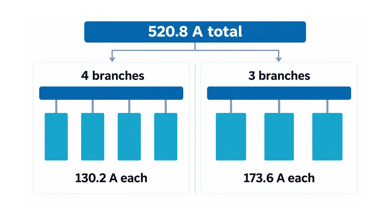
The minimum-voltage current is one-third higher than the nominal-voltage estimate. With a branch unavailable, full output would also exceed the assumed 150 A branch limit even though the common current has not increased.
If the design permits three-branch operation, an ideal equal-sharing branch-current limit gives:
P_AC,out,max = n_available × I_branch,allowed × V_DC × η_dis
At 600 V, three branches and 150 A each:
P_AC,out,max = 3 × 150 × 600 × 0.96 = 259.2 kW
This is an arithmetic ceiling under the stated assumptions, not an approved dispatch limit. Real imbalance, thermal limits, battery restrictions and PCS constraints may require lower power or may prohibit the state entirely. Increasing the common-rail copper area alone cannot authorize the remaining battery branches to carry more current.
Estimate candidate rail loss without claiming ampacity
For a uniform conductor section at an assumed calculation temperature:
R = ρL / A
P_loss = I_rms²R
where ρ is resistivity in Ω·m, L is length in metres and A is net conducting area in m². Use an appropriate material/temperature basis and account for reduced sections and interfaces separately. This calculation does not include joint resistance automatically.
For an illustrative candidate, assume:
- one 40 mm × 10 mm rail section, area 400 mm² = 0.0004 m²;
- conductor length 0.60 m;
- calculation resistivity 2.0 × 10⁻⁸ Ω·m, a deliberately stated exercise input rather than a material certificate;
- DC current treated as constant, with ripple omitted.
Then:
R = (2.0 × 10⁻⁸ × 0.60) / 0.0004 = 30 μΩ
| Current case | Conductor loss per rail | Resistive drop per rail |
|---|---|---|
| 390.63 A nominal-voltage case | 4.58 W | 11.72 mV |
| 520.83 A minimum-voltage case | 8.14 W | 15.63 mV |
If the return rail has the same resistance and carries the same current, the two-rail conductor loss in the second case is approximately 16.28 W, before joints, branch links or other components are added. The current increase makes the loss approximately 1.78 times the nominal-voltage estimate.
The resulting current-density ratio is about 1.30 A/mm², but it is only I/A for this candidate. It does not prove that the rail will stay within an allowable temperature. The separate copper-busbar ampacity guide explains why a transferable current-density rule is unreliable.
Verify heat in the complete cabinet
The loss estimate needs a thermal path. Include battery-module heat, PCS/DC equipment inside the boundary, local air temperature, joints, insulation, supports and the intended cooling arrangement. Use hot resistance consistently with the resulting temperature rather than treating the initial assumed resistivity as a verified final value.
Define the limiting component and location: a joint, insulating support, enclosure interface or nearby battery component may constrain the design before the copper itself does. Do not borrow a single generic temperature-rise allowance for every battery cabinet.
For a joint modeled as a lumped resistance, P_joint = I²R_joint. Obtain a defensible resistance and verification method for the actual joint arrangement. Different contact preparation, plating, preload and assembly tolerances are not interchangeable inputs. The connection-material and contact-loss guide explains the underlying interface issue without providing a busbar-joint acceptance value.
Where the cabinet includes a low-voltage (LV) switchgear/controlgear assembly within the International Electrotechnical Commission (IEC) 61439 scope, IEC 61439-1:2020 supplies general rules and verification requirements together with the applicable assembly part. Do not declare an entire battery system compliant merely because one distribution assembly was assessed to that series. For detailed enclosure-loss verification, use the existing compact-switchgear busbar workflow.
Cooling failure or degraded cooling also needs a defined response. Decide whether the state calls for reduced power, a timed operating limit or shutdown; do not claim that an arbitrary extra percentage of copper guarantees operation after a fan failure.
Treat DC fault duty as a separate acceptance gate
Normal operating-current limits do not establish prospective fault current. A BMS or PCS software limit is not automatically the fault-interruption mechanism for a shorted copper path.
Document the credible fault locations and contributing sources, including parallel battery branches and relevant converter/DC-link contributions. Obtain the appropriate battery and converter data across the required operating states. Establish which protective device clears each path and which parts remain supplied before complete interruption.
The verification package should address:
- prospective DC current and its time-dependent behavior at the fault location;
- interrupting ratings at the applicable DC voltage and circuit conditions;
- conductor/joint thermal withstand for the actual clearing exposure;
- peak electromagnetic loading of rails, joints and supports;
- any dependence on a specified current-limiting protective device;
- protective-device behavior for both common-rail and branch faults.
Do not apply a familiar short-circuit method outside its scope without justification. The public scope of IEC 61660-1:1997 concerns DC auxiliary installations in power plants and substations and identifies stationary lead-acid batteries among its sources. It is not a chemistry-independent lithium-ion BESS model. A qualified engineer must select a valid method for the actual system.
Coordinate insulation at maximum voltage
The current envelope and the insulation envelope use different governing inputs. Minimum operating voltage may govern constant-power current; maximum working voltage, transient conditions and the applicable insulation system govern insulation assessment.
Define clearances, creepage paths, solid insulation, pollution conditions, altitude and accessible-part protection under the applicable product/assembly rules. Coating copper does not automatically justify reducing every air or surface distance.
IEC 60664-1:2020+AMD1:2025 addresses insulation coordination within its LV scope, including equipment rated up to 1,500 V DC. Its scope is not a universal spacing table for a particular battery cabinet. IEC 62933-5-2:2025 addresses safety of grid-integrated electrochemical energy-storage systems and subsystem interactions throughout the system life cycle; it does not provide a copper cross-section by itself.
Vehicle packs add another set of mechanical and regulatory conditions. The separate EV battery busbar design guide owns that task; vehicle crash and vibration validation should not be substituted for stationary cabinet acceptance.
The final specification should contain more than dimensions
Retain the voltage/power/current envelope, allowed branch states, per-segment current, charge/discharge duty and current-sharing assumptions. Add the candidate geometry, material and joint details; the thermal verification and cooling response; DC fault/protection evidence; insulation basis; and assembly/system safety responsibilities.
Release the design only when those records support the intended operating envelope. If a branch state, hot-joint limit, fault contribution or protection response remains unknown, the result is a provisional sizing candidate—not a verified busbar rating.
References
- Sandia National Laboratories — DOE Energy Storage Handbook, Chapter 13: Power Conversion Systems
- IEC 61439-1:2020 — LV assembly general rules
- IEC 61660-1:1997 — DC auxiliary-installation short-circuit calculation scope
- IEC 60664-1:2020+AMD1:2025 — Insulation coordination
- IEC 62933-5-2:2025 — Grid-integrated electrochemical storage system safety