

An arc-flash label is useful only when its information applies to the equipment and operating conditions under review. Trace it to the equipment identity, study revision, credible supply and switching configurations, installed protective devices and their active settings. A recent date or an intact sticker cannot establish those matches.
This workflow is for facility engineers and electrical-safety program owners maintaining labels on industrial three-phase alternating-current (AC) systems. It assumes a qualified calculation study already exists. It does not calculate incident energy, prescribe a universal label layout or authorize work on energized equipment. A label is neither an isolation record nor an energized-work permit.
Treat the label as the end of a traceable chain
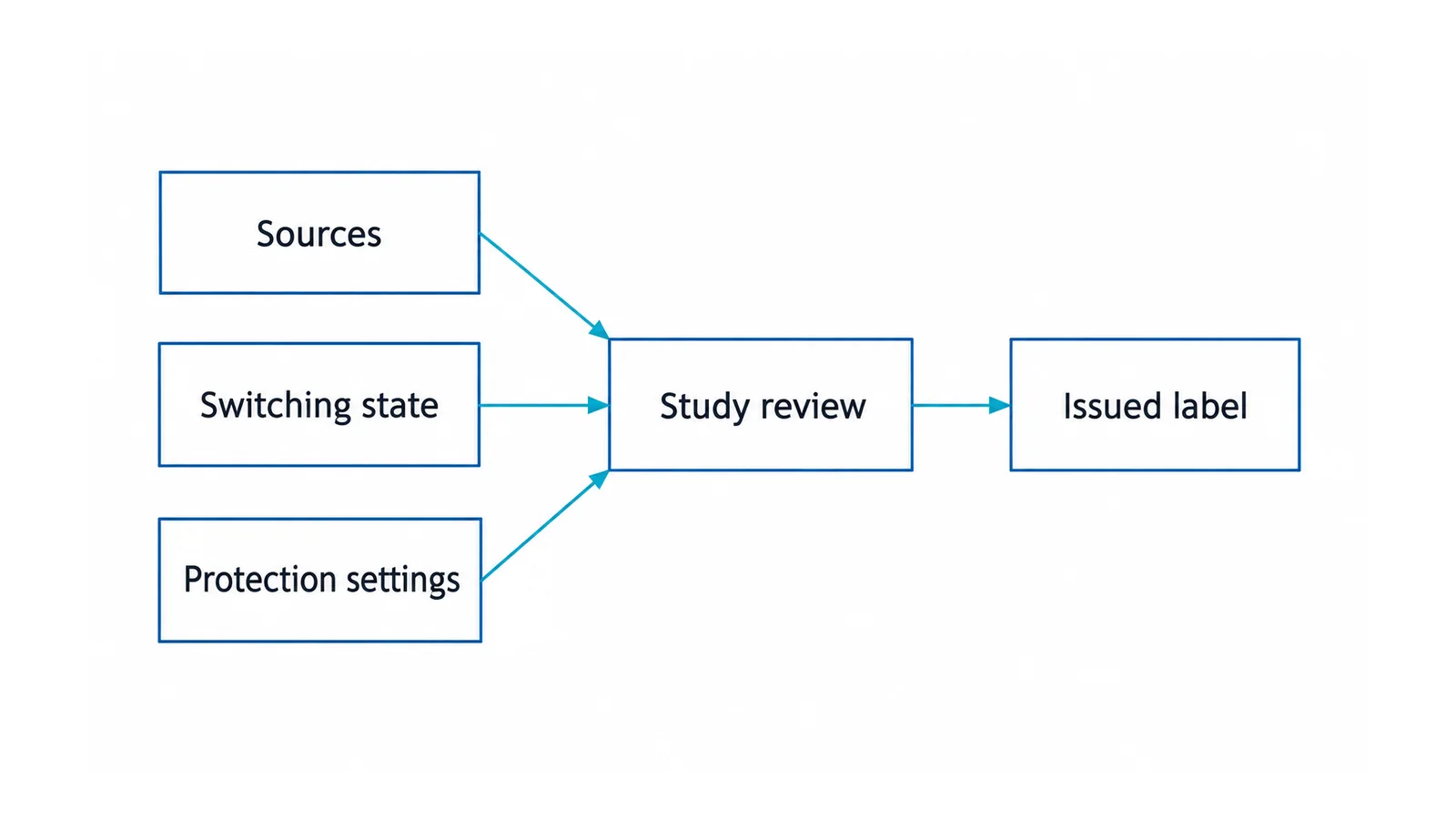
The chain is physical equipment → verified system data → modeled configuration → study result → issued label → task assessment. A break anywhere in that chain needs resolution, even if the printed value looks plausible.
The Institute of Electrical and Electronics Engineers (IEEE) standard IEEE 1584.1-2022 addresses specification of the scope and deliverables of an arc-flash hazard calculation study performed in accordance with IEEE 1584. Its public catalog is a useful scope reference; it does not establish that a particular site study has collected the right data or covered every permitted operating configuration.
The US Occupational Safety and Health Administration (OSHA) 29 CFR 1910.335 addresses necessary warning signs, tags and related safeguards. Determine detailed label requirements from the applicable electrical-safety and installation standards and their adopted editions. Do not treat a preferred site template as a universal legal requirement.
A documented example of a broken data chain
A September 2015 Department of Energy evaluation of Facility Engineering Services at the National Security Campus reported that some installed fuses differed from the fast-operating types in design drawings. The report identified increased arc-flash potential and a mismatch with the labeled hazard. It described checking the as-built equipment, recalculating and updating labels and drawings. DOE facility evaluation, section 4
This is an attributed historical finding, not an OHELE field investigation or a statement about the facility today. Its lesson is about configuration control: correct-looking paperwork cannot compensate for different installed protection. Do not copy any historical interim personal protective equipment (PPE) practice into a current job.
Step 1: resolve equipment identity and the protected location
Match the label to a stable asset identifier and the correct study bus or location. Similar names, adjacent cabinets and replacement sections deserve particular care.
Check whether the information applies to the line side, load side or another defined zone. An open main breaker may disconnect one path while leaving its line-side connections energized. Do not transfer a lower-energy result from a downstream bus to an upstream location because both are inside one cabinet.
Use drawings, existing records and safely accessible identifiers first. Any physical data collection requiring exposure to electrical hazards must follow a separately planned qualified-person procedure. A label audit is not authorization to remove a cover.
Record uncertainties explicitly. An unresolved equipment identity is not a reason to select whichever label reports the larger number and proceed.
Step 2: make an operating-configuration matrix
List the credible configurations that the facility permits. Do not invent a configuration simply because a study program can model it, and do not omit one because operators use it only during an outage.
For a hypothetical facility, the matrix might begin as follows. Every row must be confirmed against the real plant; none is an actual study result.
| Configuration | Source and switching evidence | Protection state to evaluate | Label-applicability question |
|---|---|---|---|
| Normal utility supply | Actual source data and intended feeder/tie positions | Normal installed settings | Does the study cover this equipment in this configuration? |
| Generator supply | Approved transfer arrangement and generator contribution data | Settings/functions used during generator operation | Is generator operation a covered case, rather than assumed equivalent to utility supply? |
| Authorized closed-tie operation | Which supplies remain connected and which devices clear each contribution | Active protection for the interconnected system | Is the permitted tie state included and correctly identified? |
| Bypass or temporary supply | Exact bypass path or approved temporary arrangement | Protection actually in the resulting path | Is there a reviewed result for the location under this altered path? |
Treat maintenance-state protection as an additional dimension, not a fifth supply source. A normal-utility row may require both normal-protection and approved-maintenance-state evaluations. The relevant combination is supply/switching configuration × protection state × work location.
A dated Duke University engineering specification, from May 2015, illustrates an institutional approach requiring normal, emergency and applicable bypass modes to be modeled. It is not current universal code guidance; its historical calculation settings and numerical thresholds should not be transplanted into a new study.
Step 3: confirm installed protection and conditional states
Compare the installed fuse, breaker, relay or trip unit with the device modeled in the study. Include relevant sensor or rating-plug information, settings, enabled functions and the complete clearing path. A replacement with the same ampere rating may have different operating characteristics.
Do not credit an energy-reducing maintenance setting unless its status can be established for the exact planned operation and its benefit has been evaluated. The operating procedure needs to define who can enable it, how the active state is confirmed, what happens if it is unavailable and how normal operation is restored. A command on a screen is not, by itself, evidence that the complete protection function is active.
The overcurrent-protection incident-energy guide explains why the modeled arcing-current response and clearing time matter. This label workflow uses that relationship to check documentation; it does not reproduce the calculation method.
Where a setting change affects coordination, retain its engineering review with the label decision. The LV selective-coordination workflow addresses that separate system requirement. Do not change settings solely to make the printed incident-energy value smaller.
Step 4: choose a label strategy that the plant can control
The responsible engineer and safety-program owner should choose how approved study results are communicated within the applicable labeling rules.
A single conservative result can simplify use when it actually covers the defined credible cases at the relevant location and working distance. Its conservatism must come from the study, not from guessing the maximum fault-current case. Different current and protection responses can produce different governing energy cases.
Mode-specific information can make the conditions clearer, but it introduces a human and configuration-control requirement: the user must reliably identify the active approved mode. Do not display a lower-energy maintenance-state result without its conditions or without a dependable means of confirming that state.
Linked records can provide the configuration matrix, study revision and supporting detail. A QR code or digital drawing is supplemental information, not proof that the physical plant matches the record. Consider access during an outage, unreadable labels and unavailable networks. Keep mandatory information available as required by the applicable rules.
Whichever approach is chosen, identify the study basis unambiguously and avoid conflicting old and new labels. Do not invent a PPE category by rounding or translating an incident-energy number. The approved safety framework governs worker protection.
Step 5: make changes trigger review before reliance
| Change or finding | What needs review | Immediate program action |
|---|---|---|
| New source, transformer or revised utility fault data | Relevant study inputs and affected configurations | Route the change to the study owner |
| Different protective device or settings | Installed response and all affected clearing paths | Verify as-built data before relying on old results |
| Tie, transfer or bypass procedure changes | Newly credible configuration combinations | Update the permitted-mode matrix |
| Added motors, converters or storage | Relevant contribution and clearing behavior | Obtain appropriate equipment/system data |
| Impaired protection or questionable equipment condition | Whether credited functions and assumptions remain defensible | Refer the task for qualified reassessment |
| Unreadable, missing, contradictory or misidentified label | Identity, applicable result and warning communication | Control the affected work until resolved |
OSHA’s arc-flash guidance explains that maintenance condition can undermine calculated results and calls for incident-energy reassessment after major system or equipment modifications. Scheduled review is also important, but a calendar interval is not permission to ignore an intervening change.
If a configuration is unstudied or uncertain, do not improvise an energy value, borrow a neighboring label or infer that a low-voltage bus has negligible risk. Escalate to the responsible electrical engineer and safety authority. Establish an electrically safe work condition where practicable; any necessary switching or verification still requires its own risk controls.
Step 6: close the record, not just the sticker job
Before release, retain:
- the asset and study-location mapping;
- the approved configuration/protection-state matrix;
- verified device data and settings;
- study revision and applicable results, including working-distance basis;
- the label strategy, installed label record and obsolete-information disposition;
- change-review approval and updates to affected work procedures.
The acceptance test is whether a qualified person can trace the information to the actual permitted operating condition. Reprinting a sticker does not meet that test by itself.
Use the arc-flash study overview when the study scope needs to be rebuilt, and the arc-rated PPE inspection guide when checking the condition of equipment selected by the safety program. Label accuracy, task authorization and PPE condition are separate prerequisites.
References
- IEEE 1584.1-2022 — Scope and deliverables for arc-flash calculation studies
- OSHA 29 CFR 1910.335 — Safeguards for personnel protection
- DOE — September 2015 Facility Engineering Services evaluation
- Duke University — Arc-Flash Studies specification, May 2015
- OSHA — Protecting Employees from Electric-Arc Flash Hazards