
An effective arc-flash control plan separates three functions: preventing an initiating fault, reducing a person’s exposure or the fault’s duration, and limiting the consequences of an internal arc. Maintenance preserves these functions; it does not make every energized task safe. A closed cabinet door, a fast-trip feature or an arc-resistant claim is not sufficient evidence on its own.
This article helps plant electrical engineers evaluate controls for industrial alternating-current (AC) switchgear, especially low-voltage (LV) assemblies. It is not an incident-energy calculator, a personal protective equipment (PPE) selection chart or permission to perform energized maintenance. United States (US) work-practice requirements and equipment-test documents from the International Electrotechnical Commission (IEC) and Institute of Electrical and Electronics Engineers (IEEE) are identified separately; local legal requirements and the adopted safety program govern the task.
Start with the task and the isolation boundary
First ask whether the work can be performed in an electrically safe work condition. Stopping a machine or opening a control switch does not establish that condition. Identify every relevant source, use the required isolation and lockout/tagout procedure, address stored energy and backfeed, and have a qualified person verify the de-energized condition.
The US Occupational Safety and Health Administration (OSHA) 29 CFR 1910.333 requires exposed live parts to be de-energized before work unless the specified exceptions apply. It also addresses verification and treats de-energized parts without the required lockout/tagout controls as energized. A label or installed mitigation system does not create an exception to that work-practice rule.
The switching and verification needed to establish a safe condition can themselves involve hazards. Plan those steps under the appropriate qualified-person procedure and protective measures; do not assume the final de-energized state already exists during setup.
Keep the three control functions distinct
| Control function | Examples to evaluate | Evidence needed before crediting the measure | Important boundary |
|---|---|---|---|
| Prevent initiation | Sound insulation, controlled contamination, secure connections, suitable barriers and correct equipment application | Condition records, repair closure and installation suitability | Good condition lowers opportunities for failure; it does not prove that an arc is impossible |
| Reduce exposure | Remote operation or racking, different task layout, removal of unnecessary personnel | Defined task, operator location, accessible boundaries and a reliable operating procedure | Moving a control button does not automatically put its operator outside every hazard |
| Reduce duration | Appropriate fast protection, maintenance-state settings, verified detection-and-trip schemes | Study, installed settings and end-to-end clearing-chain evidence | A relay issuing a trip is not the same as complete interruption of every source |
| Manage internal-arc consequences | Tested enclosure construction, barriers, pressure-relief arrangements or integrated active protection | Applicable test report and installation/application conditions | Performance is conditional on the tested arrangement and protected areas; it is not a universal safe-working rating |
| Protect against residual exposure | Task-specific arc-rated PPE, shock protection and access controls | Hazard assessment, correctly selected equipment, training and condition checks | PPE does not remove the hazard or repair failed equipment |
This matrix is a design-review framework, not a ranking of brand features. OSHA’s arc-flash guidance places controls in a hierarchy and explains why equipment condition and protective-device performance matter to the assessment. Its recommendations are guidance, not a new regulation.
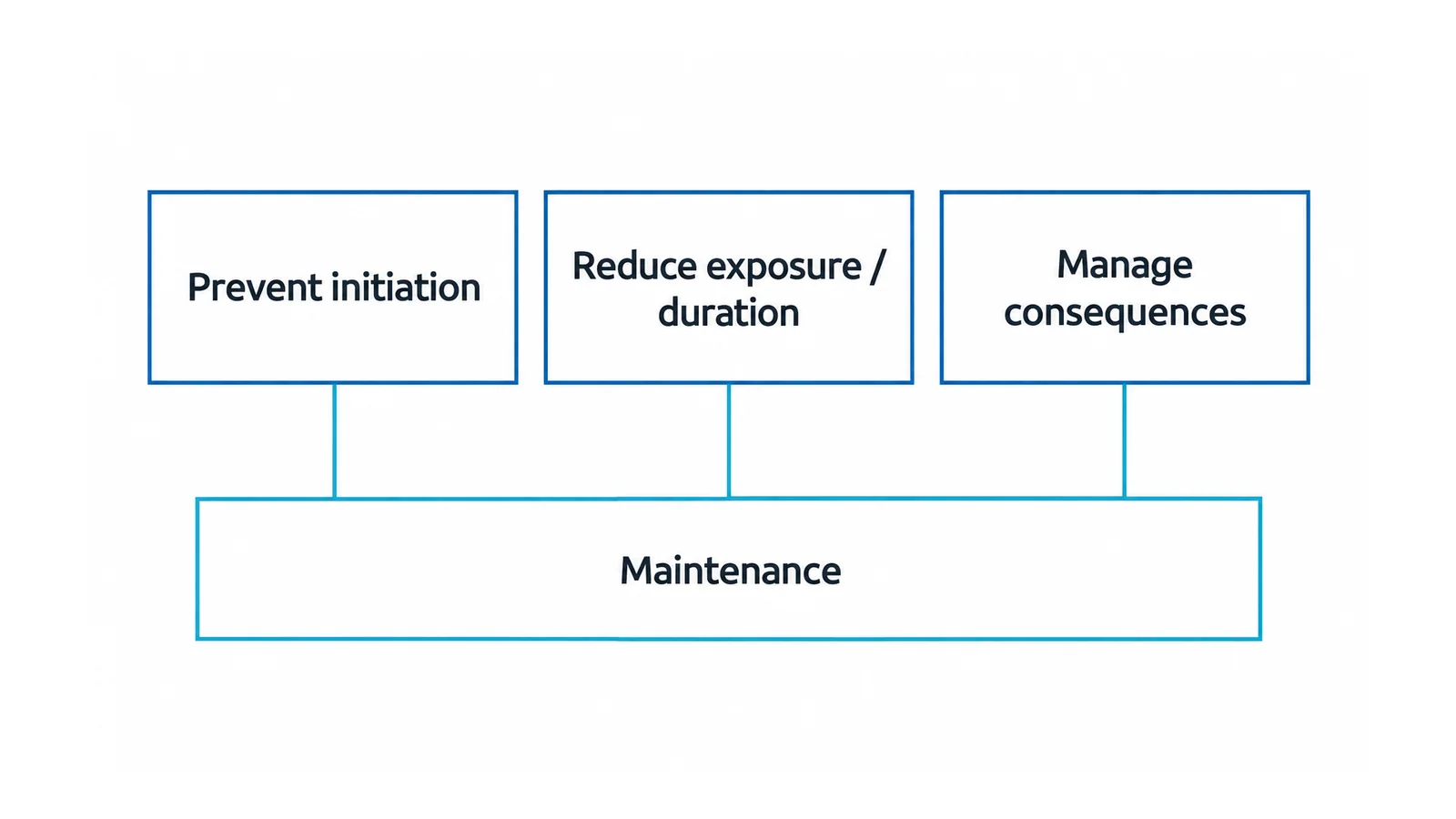
Maintenance preserves assumptions in the protection system
An arc-flash study uses a modeled clearing response. If a breaker, trip circuit or detection system cannot deliver that response, the modeled benefit is not an assured physical result. Maintenance should therefore be tied to the functions on which the assessment relies, not only to the appearance of the enclosure.
Build the maintenance review around three questions:
- Initiation: are insulation, connections, supports and environmental controls in the condition assumed by the design?
- Detection and clearing: do the sensors, protection settings, power supplies, logic, trip path and interrupting equipment remain consistent with the scheme?
- Consequence control: are the barriers, fastening arrangements, doors and any required relief path intact and installed as intended?
The needed inspection and test methods depend on the equipment and scheme. A settings download, a functional trip command and a breaker timing result are different pieces of evidence; none should be silently substituted for the others.
Do not open energized equipment merely to obtain a better inspection view or tighten a suspect connection. Warning signs, damage or an overdue critical verification should trigger a qualified assessment and appropriate controls. For equipment with persistent condition or supportability problems, the repair, retrofit and replacement guide addresses a different decision: whether the existing asset remains a defensible platform.
Evaluate faster-clearing technology as a complete chain
The causal path is detection → logic → trip command → opening/interruption → removal of all relevant source contributions. Define which part a proposed technology changes.
A maintenance-state setting may alter the protection response for an approved task. Before using its calculated benefit, verify that the intended state is active, the installed device and settings match the study, the relevant fault is within its protection reach, and the state can be controlled and restored under the operating procedure.
An internal-arc detection scheme similarly needs more than a sensor demonstration. Ask which zones are detected, how the logic distinguishes the intended event, which device interrupts it, what power supplies the chain, and how multiple sources are cleared. Check the consequences of a failed channel, unavailable trip supply or disabled function.
Shorter duration generally reduces predicted thermal exposure for the same modeled arcing condition, but a protection change can also alter the relevant operating cases. Do not scale an old incident-energy number by a trip-time ratio and call the study updated. The dedicated overcurrent-protection and incident-energy explainer covers the clearing-time mechanism; a qualified study must evaluate the actual system.
Remote operation addresses a different part of the problem: personnel exposure. Establish where the person will stand, the equipment’s applicable protection/venting arrangement, access control and the exact operation. No universal safe distance follows from the words remote control.
Containment depends on assembly evidence and installation conditions
Arc-resistant equipment is evaluated for internal-arcing performance under defined conditions. It is not an assertion that every face, compartment, open-door condition or maintenance task is protected.
Ask for the relevant test evidence and application conditions, including:
- the assembly and zones or accessibility arrangements to which the result applies;
- the tested fault duty and duration, with the actual system duty assessed against it;
- required door, cover, latch and barrier configurations;
- specified clearance, pressure-relief, exhaust or room arrangements where applicable;
- permissible installed changes and the effect of cable entries or added equipment;
- protection-system dependencies where active measures contribute to performance.
These are review questions, not identical mandatory features of every design. A blocked exhaust path or an undocumented enclosure modification can invalidate the intended installation basis; evaluate the actual documentation before crediting the result.
The current official catalog describes IEEE C37.20.7-2024 as a recommended practice for testing switchgear rated up to 52 kV for internal arcing faults, including performance evaluation and equipment application. A catalog reference establishes scope, not a certificate for a particular cabinet.
A current IEC boundary worth checking
IEC TS 61641:2026, published on 19 August 2026, addresses internal arc-fault protection of LV assemblies within the IEC 61439 series. Its public scope distinguishes passive construction, integrated active protection and arc-ignition-protected zones. It replaces IEC TR 61641:2014 and IEC TS 63107:2020.
The same scope explicitly excludes maintenance-work conditions and PPE, along with certain other effects such as toxic-gas emissions, loud noise and intense light. It also does not cover integration of household-type arc fault detection devices under IEC 62606. An assembly claim under this document therefore cannot serve as a task-specific PPE decision or as proof that ordinary household arc-fault protection provides equivalent assembly protection.
This is a verified scope summary, not a clause-by-clause interpretation of the full technical specification. Confirm the applicable edition and the exact evidence used for the installation. A newer publication does not, by itself, require replacement of every older tested assembly.
Keep a three-part assurance record
A useful plant record connects equipment, protection and work:
- Equipment record: identity, condition findings, applicable internal-arc evidence, installation restrictions and documented modifications.
- Protection record: study revision, installed devices/settings, mode dependencies, required verification results and unresolved impairments.
- Task record: the proposed operation, isolation approach, exposure conditions, access controls and qualified-person safety decision.
Give each unresolved item an owner and a disposition. If a credited function cannot be demonstrated, do not continue using its claimed benefit by assumption; refer the task and study to the responsible electrical-safety authority.
For the analytical boundary, see what an arc-flash study does. For residual worker protection, use the separate arc-flash PPE selection guide with the applicable assessment and safety program. The final question is whether the complete task has defensible controls—not whether the cabinet has enough protective features on a specification sheet.