
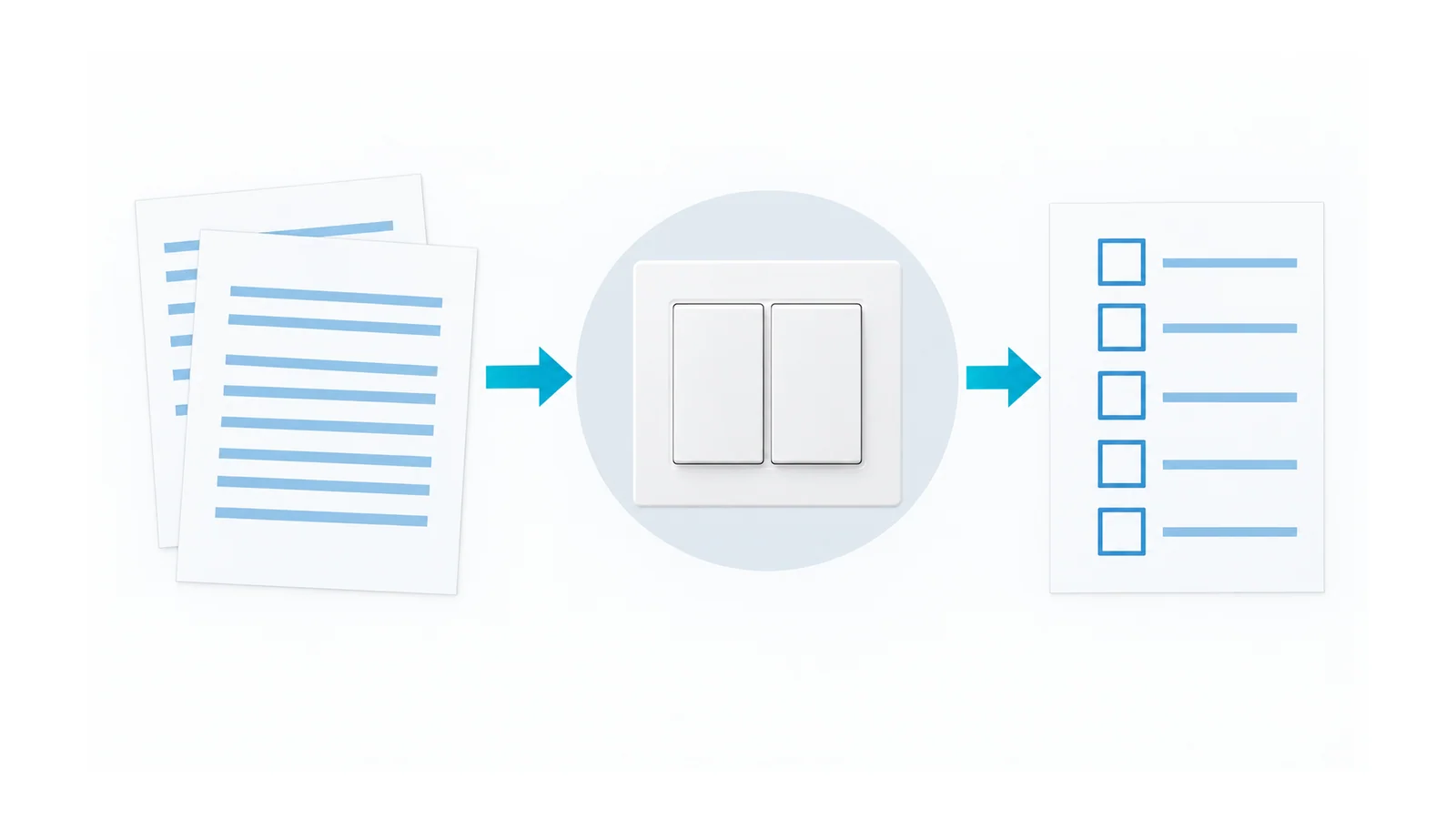
A modular switch or socket installation is ready for handover only after five questions have documented answers: is the accessory system suitable, was the work safely isolated, are the terminations correct, is the assembled enclosure intact, and has the installation been properly verified? A lamp turning on answers only a functional question.
This workflow is for competent electrical installers and engineers reviewing household and similar fixed low-voltage accessories. It is an acceptance checklist, not a terminal-by-terminal wiring guide. National installation rules, approved product instructions and the project’s verification requirements determine the details. No universal conductor colors, strip lengths, torque values or pass/fail test numbers are supplied here.
Do not use this article to begin live work. Isolation, absence-of-voltage verification, appropriate protective equipment and controlled re-energization require trained personnel and the applicable safe-work procedure.
Product standards and installation verification answer different questions
Modular describes a mechanical arrangement: functional inserts fit into a compatible support and faceplate system. It is not a safety classification, and similar-looking inserts from different ranges are not automatically interchangeable.
The International Electrotechnical Commission (IEC) references below concern product or installation scope; they answer different questions.
| Reference or document | Question it helps answer | What it does not establish by itself |
|---|---|---|
| IEC 60669-1:2017 | Which general-purpose manually operated alternating-current (AC) fixed-installation switches are within its scope? | Suitability of every electronic control, load or installed circuit |
| IEC 60669-2-1:2021 | Which electronic control devices have particular requirements? | That a particular dimmer or electronic switch will operate every light-emitting diode (LED) driver correctly |
| IEC 60884-1:2022 | Which household/similar AC plugs and socket-outlets are covered? | Acceptance of every national socket system or assembled installation |
| IEC 60364-6 series, as applicable locally | How installation verification is addressed | Product certification or an accessory-specific wiring instruction |
| Product instructions and conformity evidence | Permitted module combinations, loads, conductors and installation conditions | Verification of the completed building circuit |
The official catalogs identify the scopes of IEC 60669-1, IEC 60669-2-1 and IEC 60884-1. They are not certificates for an accessory bearing those numbers. The catalog for IEC 60364-6:2016 identifies initial and periodic installation verification; use the edition and national adoption applicable to the project, rather than assuming the catalog edition overrides local rules.
Gate 1: establish compatibility before work starts
Record the exact accessory range and module references. Confirm that the insert, support frame, faceplate and back box form a permitted combination. Check depth, mounting, conductor space and any environmental sealing arrangement. A module that clips into a frame can still be an undocumented combination.
Then match electrical duty to the accessory:
- supply voltage and frequency;
- socket system, protective-contact arrangement and applicable national approval;
- load type and permitted switching duty, not only a headline ampere rating;
- electronic-control compatibility, including any neutral requirement and load restrictions;
- environment, ingress protection and any special-location restrictions;
- circuit conductors and the installed protective-device arrangement.
A mechanical switch, an electronic dimmer and a smart control are not interchangeable merely because they occupy the same module width. Treat the load and supply requirements as separate checks.
Hold point: missing instructions, uncertain module compatibility, unsuitable location or an unexplained circuit/protection mismatch. Resolve these before installation. Do not compensate for unsuitable equipment with a larger protective device.
Gate 2: identify and secure the actual isolation boundary
The installer must establish which circuit or circuits feed the box, including any separate supply or backfeed relevant to the work. A wall switch in its off position, a dark lamp or a display showing zero power does not prove isolation at the terminals.
Follow the approved procedure to disconnect and secure all relevant supplies, prevent re-energization, verify absence of voltage at the work location with suitable test equipment, and control adjacent live hazards. Instrument suitability and proving arrangements are part of the procedure, not optional accessories.
The UK Health and Safety Executive (HSE)’s HSG85 safe-working guidance, especially its working-dead and proving-dead sections, explains these boundaries. It does not recommend a non-contact voltage indicator as the means of proving a low-voltage circuit dead. Its guidance is not a substitute for another jurisdiction’s adopted work rules.
Hold point: circuit identity uncertain, isolation cannot be secured, verification cannot be completed, or adjacent hazards are uncontrolled. Stop and escalate; do not work around the uncertainty by using insulated tools alone.
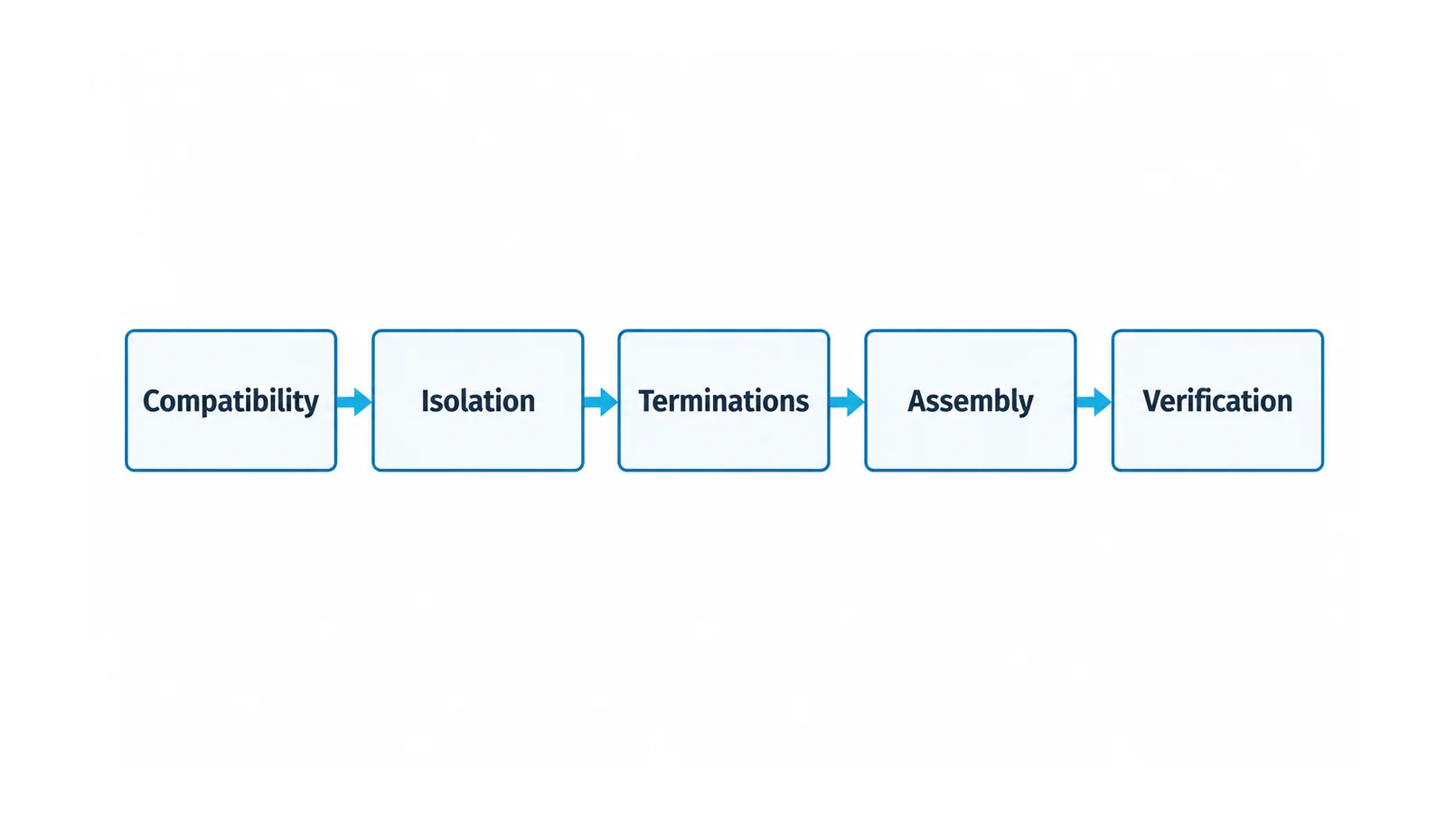
Gate 3: verify terminations against the exact instructions
With the safe-work condition established, check the permitted conductor material, cross-section and conductor class for each terminal. Confirm the number of conductors permitted in a terminal, the preparation method, strip length and any ferrule requirement or prohibition. Follow the stated tightening method for screw terminals and the specified insertion/release method for spring terminals.
Do not borrow a torque value from a different module or use a ferrule simply because one is used elsewhere in the building. Terminal suitability changes with the actual interface. The principles in solid versus stranded conductors at terminal blocks are useful background, but a terminal-block allowance does not transfer automatically to a switch terminal.
Check for insulation trapped under a contact, exposed conductor beyond the permitted termination, damaged strands or a conductor that is not retained correctly. Account for feed-through connections, where present: the conductor path and terminal arrangement must be permitted, not inferred from space in the back box.
Where protective earthing or bonding is required, verify the intended path to relevant exposed conductive parts. A decorative metal plate is not evidence of an effective protective connection. UK HSE’s HSR25 guidance, under connections and earthing, explains the need for mechanically and electrically suitable connections. Actual acceptance remains governed by the installation rules and accessory construction.
Hold point: unsupported conductor type, unauthorized doubling of conductors, damaged terminations or uncertain protective continuity. The LV termination guide explains interface failure mechanisms; it is not a substitute for the module’s instructions.
Gate 4: check the complete assembly, not just the insert
Before controlled energization, inspect the final assembly for the conditions that installation may have introduced:
- inserts properly secured in the correct support;
- faceplate correctly fitted, with no unintended access to live parts;
- no pinched insulation or conductors displaced by plate screws;
- adequate space for conductors without forcing the module into the box;
- protective connections undisturbed by assembly;
- intended shutters, barriers and seals intact;
- labeling or circuit identification sufficient for operation and future maintenance.
A visual check cannot certify hidden contact pressure or protective-device performance, but it can catch assembly defects that a successful functional test might miss. Document any deviation rather than forcing a cover to close over it.
Hold point: the assembly closes only under strain, a barrier is damaged, a seal is incomplete or a protective connection changes when the plate is fitted.
Gate 5: complete installation verification and controlled handover
The competent verifier should identify the inspections and tests applicable to this installation or alteration. Depending on the circuit and local rules, the record may address protective-conductor continuity, polarity, insulation, the protective measure against electric shock, relevant protective-device operation and function. These are categories of evidence, not a universal test sequence.
Choose the method and test voltage for the actual circuit, particularly where electronic modules or connected equipment could be affected. Disconnect or otherwise protect equipment only in accordance with the permitted method. The insulation-resistance testing guide explains why test conditions and connected equipment matter.
A plug-in tester is not a complete installation-verification instrument. HSE’s electrical-safety FAQ cautions that some socket testers miss faults. Similarly, a protective device’s test button checks a particular function, not every property of the final circuit. The ground-fault circuit interrupter (GFCI) and arc-fault circuit interrupter (AFCI) comparison explains why different protective functions must not be conflated.
Energization and any necessary live verification belong to a separately controlled, qualified-person procedure with the required protective measures. This checklist does not authorize energized testing. Handover follows satisfactory results and resolution of defects, not an arbitrary deadline.
A compact acceptance record
| Gate | Evidence retained | Release decision |
|---|---|---|
| Compatibility | Module/support identifiers, instructions, duty and location checks | Suitable documented combination |
| Isolation | Circuit identity and safe-work verification record required by the procedure | Work boundary established |
| Terminations | Conductor/terminal suitability and completed connection checks | No unresolved interface or protective-path defect |
| Assembly | Enclosure, mounting, barriers, seals and conductor-space inspection | Assembly intact in its final state |
| Verification | Applicable inspection/test results, defect closure and responsible-person sign-off | Authorized for handover |
Keep this record with the installation documentation. Include the affected circuit, location, accessory references, applicable rules, verifier and any remaining operating limitations. The useful result is a traceable accepted installation—not merely five boxes ticked.
References
- IEC 60669-1:2017 — General-purpose fixed-installation switches
- IEC 60669-2-1:2021 — Electronic control devices
- IEC 60884-1:2022 — Household and similar plugs and socket-outlets
- IEC 60364-6:2016 — Installation verification
- HSE HSG85 — Electricity at work: Safe working practices
- HSE HSR25 — Electricity at Work Regulations guidance
- HSE — Electrical-safety frequently asked questions