
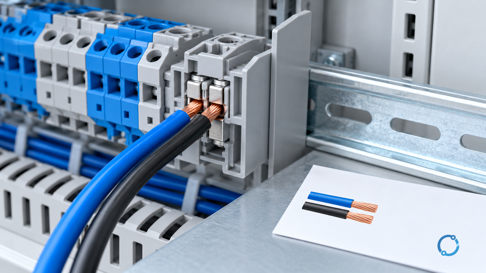
Two conductors can share one terminal block only when the exact terminal arrangement is rated and approved for that conductor pair. That sentence deliberately separates two conditions that are often confused: a terminal block may have several electrically connected clamping positions, while a single clamping point may be approved for one conductor only.
The safe decision is not “yes, if the wires fit.” It is:
- identify whether both conductors enter the same clamping unit or separate positions;
- obtain the terminal manufacturer’s instruction for the exact product and accessory configuration;
- match conductor material, size, class, preparation and insertion direction;
- verify current sharing, temperature, insulation and panel approval for the complete arrangement;
- inspect and record what was actually installed.
If any of those items is unknown, hold the connection and obtain product or engineering evidence. This article provides a verification workflow; it does not create a universal conductor combination, torque value or current rating.
Start with the physical connection, not the terminal family
“Two wires in one terminal” can describe several different constructions:
| Proposed arrangement | What must be proved |
|---|---|
| Two conductors clamped directly under one screw or spring | The exact product permits that conductor combination at one clamping point |
| Two conductors inserted into two separate positions in one terminal block | The positions are electrically common and each position accepts its assigned conductor |
| Two terminal blocks connected by a jumper or bridge | Every terminal, conductor and accessory is compatible with the intended current path |
| Two conductors joined with a separate connector, then one conductor enters the terminal | The connector is suitable for the environment, voltage and current, and the terminal sees a valid terminated conductor |
| One conductor passes through a current transformer and another is used for control | The power and control functions remain electrically and physically separated as required |
The phrase “one terminal block” does not answer which of these constructions is being proposed. A photograph of a similar block is not enough because variants may use different current bars, springs, screws, barriers, covers, jumper systems and test functions.
IEC 60947-7-1:2025 covers terminal blocks for copper conductors within a defined industrial scope. It is useful for identifying the product family and the evidence that should exist. It does not state that every terminal in the family accepts any pair of wires, any mixed conductor sizes or any accessory stack.
Gate 1: define the electrical function
Record the purpose of the connection before evaluating the clamp:
- phase, neutral or protective conductor;
- power, control or signal circuit;
- fused or unfused function;
- test-disconnect point;
- current-transformer or voltage-transformer circuit;
- isolated barrier or functional separation;
- feed-through, distribution or jumper connection.
These functions can require different terminals. IEC 60947-7-2:2009 addresses protective-conductor terminal blocks with PE and PEN functions within its scope. IEC 60947-7-3:2009 addresses fuse terminal blocks. A general-purpose feed-through terminal is not automatically a protective-conductor or fuse terminal.
For protective conductors, the question is not merely whether two green-and-yellow wires fit. The protective-conductor terminal must have the correct function, conductor range, mounting contact and installation arrangement. For a fused terminal, the fuse-link rating and the terminal’s complete product data also belong to the connection decision.
Gate 2: identify the clamping unit and current path
For the exact product, obtain a current data sheet, instruction sheet and dimensional drawing. Mark the clamping points on the drawing. Then trace the electrical current path between the proposed conductors.
Ask:
- Do both conductors touch the same clamping saddle, screw, spring or cage?
- Are they inserted from the same side or opposite sides?
- Does a partition separate the two positions?
- Is the connection through a removable jumper, bridge, distribution block or insulated bus?
- Does the current pass through a marking strip, test plug, fuse holder or other accessory?
- Is the jumper rated for the full load and fault current that the design requires?
- Does one conductor obstruct the insertion, clamping or inspection of the other?
The article on terminal block selection for electrical panels provides a broader method for matching terminal function to panel design. Use it after the physical connection has been defined, not as a substitute for the exact product instruction.
Gate 3: compare both conductors with the declared range
A two-conductor decision needs a two-conductor record. Create one row for each conductor:
| Input | Conductor A | Conductor B |
|---|---|---|
| Material | Copper or declared alternative | Copper or declared alternative |
| Construction | Solid, stranded, flexible or fine-stranded | Solid, stranded, flexible or fine-stranded |
| Cross-section | mm² or AWG/kcmil | mm² or AWG/kcmil |
| Insulation and temperature | Product and insulation class | Product and insulation class |
| Preparation | Stripped, ferrule, tinned or other | Stripped, ferrule, tinned or other |
| Termination | Correct ferrule or cable end | Correct ferrule or cable end |
| Insertion depth | Per product instruction | Per product instruction |
| Direction | Same or opposite insertion side | Same or opposite insertion side |
IEC 60947-7-1’s scope is built around copper conductors within specified ranges. That does not make an aluminum conductor interchangeable. Aluminum has different oxide, creep, galvanic and preparation requirements, and a mixed copper-aluminum joint may require an approved transition.
Two conductors of the same nominal cross-section can still differ in strand class, ferrule, insulation diameter or termination method. Conversely, two different cross-sections may be allowed in a particular terminal if the product instruction explicitly declares that combination. The product statement controls, not symmetry or appearance.
Flexible conductors should be prepared with the accessory and method specified for the terminal. A ferrule that is too long may prevent full insertion; one that is too short may leave strands outside the clamping zone. Trimming strands to make a conductor fit is a defect, not a valid adaptation.
Gate 4: verify current, heat and short-circuit duty
The terminal’s headline current rating may not be the rating of the proposed pair. The approved combination can depend on:
- conductor size and material;
- number of loaded circuits;
- continuous current per conductor and per terminal;
- unequal current sharing;
- ambient temperature;
- mounting rail and enclosure conditions;
- adjacent heat sources;
- grouping and ventilation;
- harmonics or other non-sinusoidal current;
- short-time and short-circuit duty.
The terminal standard’s test scope is not a panel-level thermal or short-circuit study. The current-rating guide explains why the installed load and derating basis matter. For an industrial control panel, the assembly approval and short-circuit coordination also need to be checked; the SCCR and panel context guide provides a starting point for that separate question.
Two conductors can also create a thermal problem that is invisible from the nominal wire size. One conductor may carry more current because of resistance differences, strand damage or a shorter electrical route. If the design relies on equal sharing, the evidence must support that assumption.
Equal voltage does not prove equal sharing
Two conductors connected to the same terminal are not guaranteed to divide current equally. Their complete circuits extend beyond the terminal into the panel wiring, routing, joints, ferrules and connected loads. A conductor with more strands, a shorter route or a cleaner termination can take more current than its neighbour even when both appear to have the same nominal size.
This is why a product statement that permits two conductors does not automatically permit any pair of loads to share them. The designer must determine:
- whether the two circuits are expected to carry equal current;
- whether one circuit can operate while the other is disconnected;
- whether the terminals remain acceptable if the load is unbalanced;
- whether the combined current and heat are covered by the terminal and panel rating;
- whether a fault on one outgoing path affects the other through the shared connection;
- whether maintenance can isolate one path without disturbing the other;
- whether the test and verification plan can prove the installed current split.
For branch distribution, it may be better to use two separate terminal positions fed from an approved distribution bar than to place two branch conductors at one clamping point. The separate positions provide clearer isolation, identification and fault containment even if the terminal blocks are electrically common. The best answer is therefore often an arrangement change, not a search for a larger screw.
One terminal block can be approved while the assembly is not
A panel contains current-carrying parts, insulation, barriers, wiring ducts, labels, bonding, short-circuit protective devices and an enclosure. A terminal block that is suitable as a component can still be unsuitable in a particular assembly because of:
- reduced clearance or creepage to an adjacent part;
- a partition or end plate that has been omitted;
- exposed live terminals after the cover is removed;
- a wire duct that blocks inspection or bends the conductor beyond its allowed radius;
- an unrated jumper or marking accessory;
- a rail that is not bonded or supported as the panel design requires;
- grouping and heat accumulation not represented in the terminal’s single-unit data;
- short-circuit current that exceeds the component or assembly basis;
- a modification that invalidates the panel listing or certification.
The terminal-block replacement checklist provides a component-level method, but a two-conductor change also needs a panel-level review. Record which approval belongs to the terminal, which belongs to the assembly and which belongs to the site installation. One certificate is not automatically evidence for all three.
Gate 5: verify accessories, barriers and accessibility
Accessories are part of the connection, not decoration. Inspect:
- end stops and end plates;
- partition plates and covers;
- jumper bars and bridge identifiers;
- test plugs, disconnect levers and actuation tools;
- marking tags and holders;
- cable ducts, glands and bend radius;
- adjacent live parts;
- access for inspection and maintenance;
- the ability to verify conductor insertion and clamping.
A jumper from one terminal to another may be electrically conductive and mechanically neat, yet still be the wrong solution if it is not rated for the current, cannot be inspected, reduces clearance or bypasses an intended isolation function. Substituting a bridge for an approved two-conductor clamping unit requires engineering review.
The distinction between terminals and separate wire connectors is also material. A connector that joins two wires outside the terminal may solve a conductor-splicing problem while creating a new insulation, strain-relief and mounting problem. See terminal blocks versus wire connectors before treating the two component classes as interchangeable.
Mixed conductor sizes and classes need their own evidence
The most common invalid assumption is that two wires fit, so the terminal must accept the pair. A product may support two conductors of the same declared range but not a combination of a large solid conductor and a small flexible conductor. It may support two conductors from opposite sides only when a particular partition, spring or current bar is present. A different revision of the same family can change the geometry.
A useful mixed-conductor review includes:
| Difference | Why it requires evidence |
|---|---|
| Different cross-sections | The smaller conductor may not receive the clamping force or current-sharing behaviour assumed by the design |
| Solid and stranded construction | Deformation, contact area and strand movement differ under clamping |
| Flexible conductor with ferrule | Ferrule length, collar and tool shape must match the terminal |
| Different insulation diameter | A large insulation body may prevent full insertion or correct seating |
| Different metals | Oxide, creep and galvanic contact behaviour can invalidate a copper-only assumption |
| Different insertion direction | The product may permit a pair only in a designated orientation |
| One wire looped or doubled back | Multiple physical contacts do not create an approved conductor combination |
If the manufacturer does not declare the exact combination, ask for a written technical confirmation that identifies the terminal revision, accessory set and installation instruction. A sales statement that a larger terminal is “usually fine” is not evidence. If the manufacturer cannot confirm the pair, change the connection design or obtain a formal engineering solution.
Current sharing and conductor heating are design duties
The terminal must carry the sum of the conductor currents through its internal current path. Each conductor must also remain within its own ampacity and termination rating. A two-conductor arrangement can pass a bench continuity check while one conductor overheats in service because the load is not shared as assumed.
The verification plan should therefore include:
- the expected continuous current in each conductor;
- the maximum unbalanced condition;
- the terminal and conductor ambient basis;
- the effect of adjacent loaded terminals;
- the conductor installation method and heat dissipation;
- the fault current and protective clearing time;
- a thermal inspection after the equipment has reached a representative operating state;
- a record of the actual load during that inspection.
Do not use an infrared image as a complete electrical verification. A cool image taken at light load cannot prove the joint will remain cool at full load or under harmonic current. A hot image can identify a location needing investigation, but the temperature limits, emissivity, measurement geometry and equipment state must be understood.
Inspection and handover after the connection is made
The decision cannot end with an approved drawing. The installed arrangement must match the approved evidence. Before release, the inspector should be able to see:
- the correct terminal family and revision;
- both conductors fully inserted and correctly prepared;
- no stray strand outside the clamping zone;
- the required ferrule, end plate and partition;
- the correct jumper or bridge if the design uses one;
- terminal markers matching the schematic;
- adequate clearance to adjacent live parts;
- no damage to conductor insulation or terminal housing;
- the specified fastening or spring operation;
- the panel cover and barrier installed as designed;
- a completed record of the exact conductor pair.
If the terminal is later replaced, a visually similar unit is not automatically acceptable. The same conductor pair may have been approved for the old clamping geometry and not for the new one. Update the panel drawing, bill of materials, terminal list and inspection record. A maintenance technician opening the panel months later should not have to rediscover why two wires were placed in one position.
Special conductors deserve a separate decision
Protective conductors
The PE or PEN function needs a product identified for that function and a conductor arrangement that preserves continuity, identification and low impedance. Do not use a spare feed-through terminal because it is nearby. Protective-conductor terminal blocks may have a direct electrical connection to the rail or may use a designated mounting and contact method; follow the exact product instruction.
Fused terminals
A fuse terminal adds a replaceable protective device to the connection. Verify the terminal’s fuse size, short-circuit data, accessories, voltage and current limitations. Two conductors do not become acceptable merely because the fuse terminal has two openings.
Fine-stranded and ferrule conductors
The terminal must accept the conductor class and the ferrule system used. The ferrule must match conductor cross-section and insertion geometry. If the product instruction requires a particular ferrule length, plastic collar or crimp profile, that preparation is part of the approval.
Mixed materials
Do not combine copper and aluminum without an explicitly approved transition method. Even where a mechanical fit appears possible, electrochemistry, creep, oxide growth and maintenance requirements differ. For general conductor-class selection, see solid versus stranded wire terminal blocks.
What the product evidence should contain
For a proposed two-conductor connection, request evidence that matches the identity of the exact item:
- complete product designation and revision;
- photograph or drawing of the clamping unit;
- permitted conductor count per clamping point;
- permitted conductor types and cross-sections;
- permitted mixed sizes or mixed classes, if any;
- required ferrules and stripping length;
- tightening torque only where the product specifies it;
- rated voltage, current and ambient conditions;
- temperature-rise or derating data for the relevant arrangement;
- short-circuit and panel-coordination evidence;
- required end plates, partitions, covers and jumpers;
- installation and reinspection instructions;
- declaration of conformity, listing or certification scope where applicable.
A terminal marking such as “2.5 mm²” is not a complete two-conductor approval. It may describe one conductor per position, a maximum range or a family rating. For a careful reading of terminal markings, see terminal-block markings under UL and IEC systems.
Installation is more than getting both wires under the screw
Once the exact configuration has been approved, installation should follow the product instruction. Typical verification points include:
- conductor length and stripping dimension;
- strand condition and correct ferrule;
- full insertion into the clamping zone;
- no contact with the wrong terminal or barrier;
- correct screw or spring operation;
- correct accessory orientation and locking;
- no damaged insulation or exposed strand bridge;
- correct terminal marking and circuit identification;
- adequate bending radius and strain relief;
- usable inspection and maintenance access.
Do not use a generic torque table to override the product instruction. Torque depends on the clamp design, thread, material, washer, conductor and tool. Over-tightening can damage the current bar or spring; under-tightening can leave a high-resistance joint. If the product does not provide a tightening value, obtain the correct instruction rather than guessing.
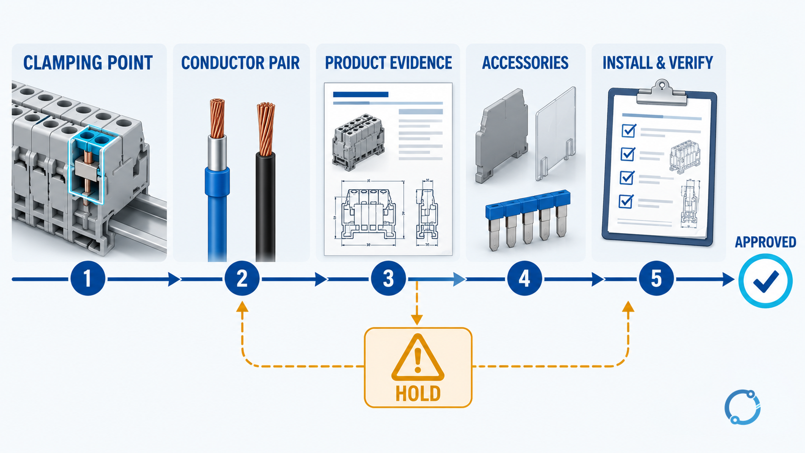
A practical approval record
The record should make the decision reproducible:
| Field | Record |
|---|---|
| Terminal function | Feed-through, PE/PEN, fused, test or other |
| Exact product | Family, type code, revision and drawing |
| Clamping configuration | One point, two positions or jumper path |
| Conductor A and B | Material, class, size and preparation |
| Accessories | End plate, partition, bridge, cover and marking |
| Electrical duty | Voltage, continuous current and fault context |
| Thermal duty | Ambient, grouping and enclosure conditions |
| Approval evidence | Datasheet, instruction, certificate or panel approval |
| Installation result | Insertion, termination and inspection result |
| Change control | Who approved the arrangement and when |
If the record says “similar terminal,” “same wire size” or “held during test,” the decision is still incomplete. Approve the actual product and configuration.
Hold conditions
Stop and escalate when:
- the terminal instruction does not explicitly permit two conductors at the proposed clamping point;
- the conductors differ in material or class without a declared combination;
- a ferrule or terminal accessory is missing or incorrect;
- a jumper is being used to create a connection not covered by the design;
- the current rating depends on a derating basis that has not been calculated;
- the panel assembly approval or short-circuit coordination would be changed;
- the connection cannot be inspected after assembly;
- evidence points to overheating, loosening, strand damage or corrosion.
Repeated tightening, adding a second conductor to a warm terminal or fitting a larger ferrule are not approved repairs. Isolate the circuit under the site procedure, determine the cause and correct the installation using the exact product and assembly requirements.
The decision in one sentence
Two conductors may share one terminal block when the exact clamping arrangement, conductor pair, accessories, thermal duty and panel context are supported by product and project evidence. They cannot share one clamping point merely because both fit.