Use terminal blocks when conductors need organized, repeatable equipment terminations, circuit identification, test access or controlled disconnection. Use a listed twist-on or other splicing wire connector when compatible building or equipment conductors need a permanent splice inside an approved accessible enclosure. Neither is a universal substitute for the other.
For U.S. work, verify the exact certification category, conductor material and range, number of conductors, solid/stranded compatibility, temperature, enclosure, field- or factory-wiring use and installation instructions. Physical fit does not establish suitability.
What is being compared?
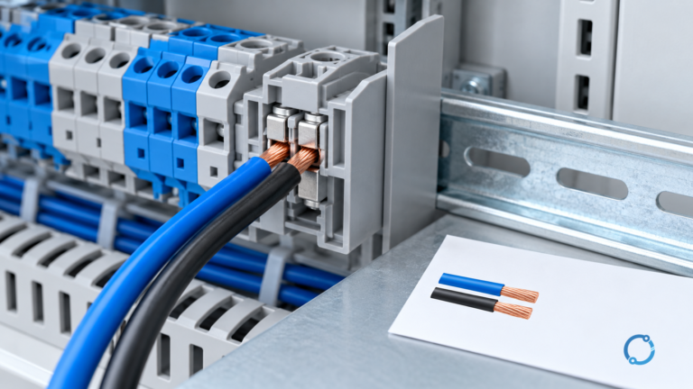
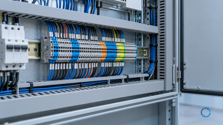
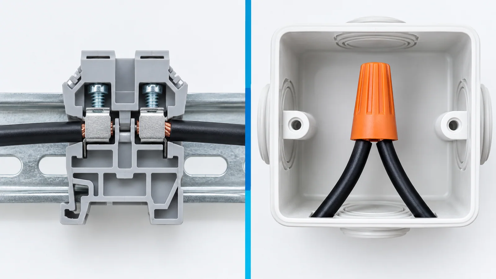
A terminal block is an assembly of terminals on an insulating support, often DIN-rail or panel mounted, that provides defined connection points. It can support marking, test plugs, disconnect functions, jumpers and repeatable field wiring.
A “wire nut” is a common name for a twist-on splicing wire connector. It joins a specific combination of conductors. Other listed splicing connectors use push-in, lever or crimp mechanisms; they remain wire connectors, not automatically terminal blocks.
UL Solutions’ connector certification page identifies UL 1059 for U.S. terminal blocks and UL 486C for splicing wire connectors, with UL 486G for sealed twist-on connecting devices. The standard and certification category must match the product and application.
Comparison table
| Dimension | Terminal block | Twist-on/splicing wire connector |
|---|---|---|
| Primary job | terminate and organize conductors at defined points | splice compatible conductors together |
| Mounting | rail, panel, PCB or equipment structure | free within an approved box/enclosure unless product instructions say otherwise |
| Circuit identification | strong; markers and terminal numbers are common | limited; splice identification is external |
| Test access | may support dedicated test/disconnect features | normally requires access to the splice |
| Reconfiguration | can be orderly if the design permits | usually remake or replace according to instructions |
| Multiple circuits | supports structured rows and segregation | each connector serves its evaluated conductor combination |
| Accessories | jumpers, end plates, barriers, test plugs | product-specific caps, sealants or accessories |
| Evidence | recognition/listing and Conditions of Acceptability | listing and marked/instructed conductor combinations |
| Typical context | panels, machines, controls, marshalling | junction boxes, luminaires and approved wiring enclosures |
Choose terminal blocks when organization is functional
Terminal blocks are the stronger starting point when:
- many field conductors enter equipment;
- circuits need durable identification;
- technicians need defined test points;
- disconnect or fused terminal functions are required;
- cross-connections use controlled jumpers;
- conductor routing and segregation matter;
- production wiring must be repeatable;
- a wiring diagram maps each conductor to a terminal number.
The block and accessories must be evaluated as used. End plates, barriers and jumpers can affect spacing, temperature and current distribution.
For U.S. panel integration, OHELE’s UL terminal-block compliance checklist explains how to trace the exact component file and Conditions of Acceptability.
Choose a listed splicing connector when the job is a splice
A twist-on or other listed splicing connector can be appropriate when:
- the connection is a conductor-to-conductor splice;
- the connector is listed for the exact materials, sizes and conductor count;
- the enclosure and access comply with the installation rules;
- the temperature and environmental rating fit;
- the installation can follow the product instructions;
- no structured test/disconnect terminal function is needed.
Do not use a twist-on connector as an improvised terminal on a device screw, bare busbar or unsupported open assembly. The connection must remain inside the approved wiring method and enclosure.
Certification status changes the answer
UL describes Recognized Components as parts intended for integration into a larger certified end product under Conditions of Acceptability. A terminal block may therefore be component-recognized rather than listed as a stand-alone field-installed product.
A splicing connector is commonly listed for field use with defined conductor combinations. The mark still does not permit arbitrary combinations.
The selection file should contain:
- manufacturer and exact model;
- certification file and category;
- country scope;
- applicable standard;
- conductor material;
- size and number of conductors;
- solid/stranded and flexible-conductor conditions;
- temperature and voltage/current conditions;
- field/factory wiring designation;
- installation instructions and required enclosure;
- accessories and environmental limitations.
Conductor compatibility is a matrix
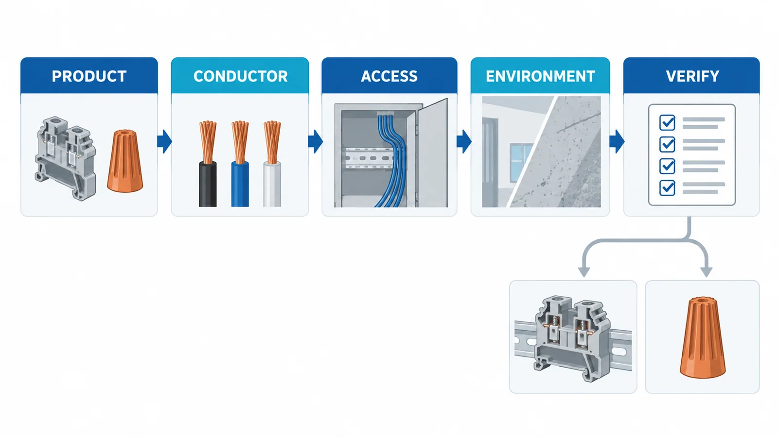
Check every dimension:
| Input | Question |
|---|---|
| Material | copper, aluminium, or a specified combination? |
| Size | are all conductors within the marked range? |
| Count | is the exact number of conductors covered? |
| Stranding | solid, stranded, fine-stranded or compact? |
| Temperature | do conductor insulation and connector ratings align? |
| Preparation | strip length, pre-twist, ferrule or no ferrule? |
| Reuse | may the connector be reused, and under what instructions? |
| Environment | dry, damp, wet, sealed, vibration or corrosive? |
Do not insert two conductors into a terminal point evaluated for one. Do not assume a connector that accepts one 12 AWG conductor accepts two 12 AWG conductors. The evaluated combination controls.
Current and temperature
For terminal blocks, current flows through a defined metal path and clamping interfaces. Temperature depends on current, conductor size, neighboring terminals, enclosure air and installation.
For splicing connectors, heating depends on contact quality, conductor combination, preparation and enclosure temperature. The circuit’s overcurrent protection must protect the conductors; the connector’s listing does not replace that coordination.
Check:
- continuous load current;
- overcurrent-protective device;
- conductor ampacity;
- internal ambient;
- grouping and adjacent heat;
- termination temperature limitations;
- abnormal current and fault path.
Never select either device solely from nominal voltage and conductor size.
Space, accessibility and inspection
Terminal blocks
Allow room for:
- conductor bend radius;
- tool access;
- marker visibility;
- barriers and end plates;
- test plugs;
- jumpers;
- rail/end-stop retention;
- separation from power components.
Splicing connectors
Allow box volume and conductor length needed to make and inspect the splice without damaging insulation. The enclosure must remain accessible where required and retain its cover and environmental rating.
A smaller connector is not automatically a smaller installed solution. The wire arrangement and service access determine the real volume.
Vibration and repeated service
Machines and vehicles can impose vibration, shock and repeated thermal cycles. Use a connection system evaluated for that environment and follow conductor-preparation instructions.
Terminal blocks can provide controlled mounting and strain management, but the exact clamping technology and accessories still require validation. A twist-on connector suitable for stationary building wiring should not be assumed suitable for machinery vibration without product and end-equipment evidence.
Example decisions
Industrial control panel
Twenty field sensors and actuators enter a panel. Circuits need numbers, test access and future replacement. DIN-rail terminal blocks with documented field-wiring suitability are the stronger choice. A bundle of twist-on splices would impair identification and may not fit the panel’s certified design.
Junction-box branch splice
Three compatible copper conductors must be joined inside an accessible dry-location junction box. A listed splicing connector whose markings cover that exact combination can be suitable. Installing a DIN rail and terminal blocks is possible only if the complete arrangement and enclosure rules are satisfied; it is not automatically better.
Wet or buried location
Neither generic option is acceptable by category name. Use a connector system specifically certified for the environment and installation method. A standard dry-location wire nut or open terminal row is not made suitable by adding tape.
Installation controls
For terminal blocks:
- verify model, accessories and certification record;
- install the rail/support and end stops;
- maintain required spacing and barriers;
- prepare conductors to the specified strip length;
- use the specified ferrule/torque/tool only when allowed;
- label and verify each circuit;
- perform production and commissioning checks.
For twist-on/splicing connectors:
- verify the exact conductor combination;
- inspect conductor material and condition;
- strip to the instructed length;
- follow pre-twist and installation instructions;
- perform the required pull/visual check;
- arrange conductors without damaging insulation;
- close the approved enclosure.
Only qualified persons should work on electrical systems under applicable isolation and verification procedures.
Stop conditions
Do not proceed when:
- the exact certification record cannot be found;
- conductor material, size, count or stranding is outside the record;
- a recognized component is being treated as a stand-alone field listing;
- the enclosure or accessibility requirement is unclear;
- the connector is being used as an unsupported equipment terminal;
- temperature or vibration exceeds the evaluated use;
- an unapproved accessory changes the connection;
- local code or the authority having jurisdiction requires a different method.
Bottom line
Terminal blocks and wire nuts solve different connection jobs. Terminal blocks create structured equipment interfaces; listed splicing connectors join approved conductor combinations inside an approved wiring method. Define the function, verify the certification category and match every conductor and environmental condition. Convenience and physical fit come after evidence.
References
- UL Solutions — Connector Certification Services
- UL Solutions — Component Recognition classification
- UL Solutions — UL 508A Supplement SA component requirements
For the feeder-sizing and installation verification framework behind this topic, see Cable Sizing for Circuit-Breaker-Protected Feeders: Six Verification Gates.