
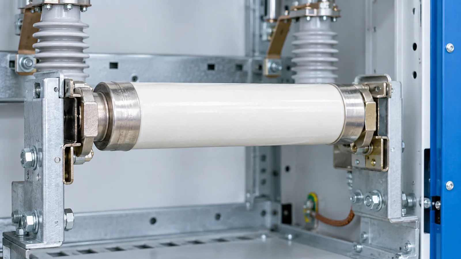
An MV fuse link has several different ratings, not one “size.” Rated voltage addresses the application voltage; rated current relates to carrying normal current under specified conditions; breaking-current ratings describe what it can interrupt within its defined operating range. A current-limiting fuse may have a minimum interrupting-current boundary, so a large maximum kA value alone does not prove that it can safely clear every lower fault or overload current. The time-current characteristic and any switch-fuse combination must also be checked.
This guide focuses on AC fuses above 1 kV. IEC 60282-1:2020 covers high-voltage current-limiting fuses for 50/60 Hz AC systems; IEC 60282-2:2008 covers expulsion fuses. They are different technologies and should not be treated as interchangeable merely because their voltage and ampere markings look similar. IEEE C37.48-2020 is an application guide covering several high-voltage fuse types and practices; it is informative, not a substitute for the applicable product standard.
Decode the schedule before comparing products
| Value or characteristic | Question it answers | Common misreading |
|---|---|---|
| Rated voltage | Is the fuse designed for the system voltage and insulation application? | “Higher voltage is always harmless” without checking coordination and assembly fit |
| Rated current of fuse link | Can it carry the intended service current under its documented thermal conditions? | Treating it as the exact operating or melting current |
| Maximum rated breaking current | What high prospective fault current can the specified link interrupt under its tested conditions? | Assuming it also covers all smaller currents |
| Minimum interrupting or breaking boundary, where applicable | What lower-current region requires another clearing path or specific class of fuse? | Ignoring a gap between overload and high-fault clearing |
| Time-current characteristic (TCC) | How does pre-arcing and clearing behavior vary with current? | Reading one point as a universal trip time |
| Cut-off current and energy let-through | What peak and thermal stress may pass during high-current operation? | Assuming every fault is current-limited to the same degree |
| Striker or indicator | How can operation be indicated or linked to a switch mechanism? | Assuming the striker is itself a circuit interrupter |
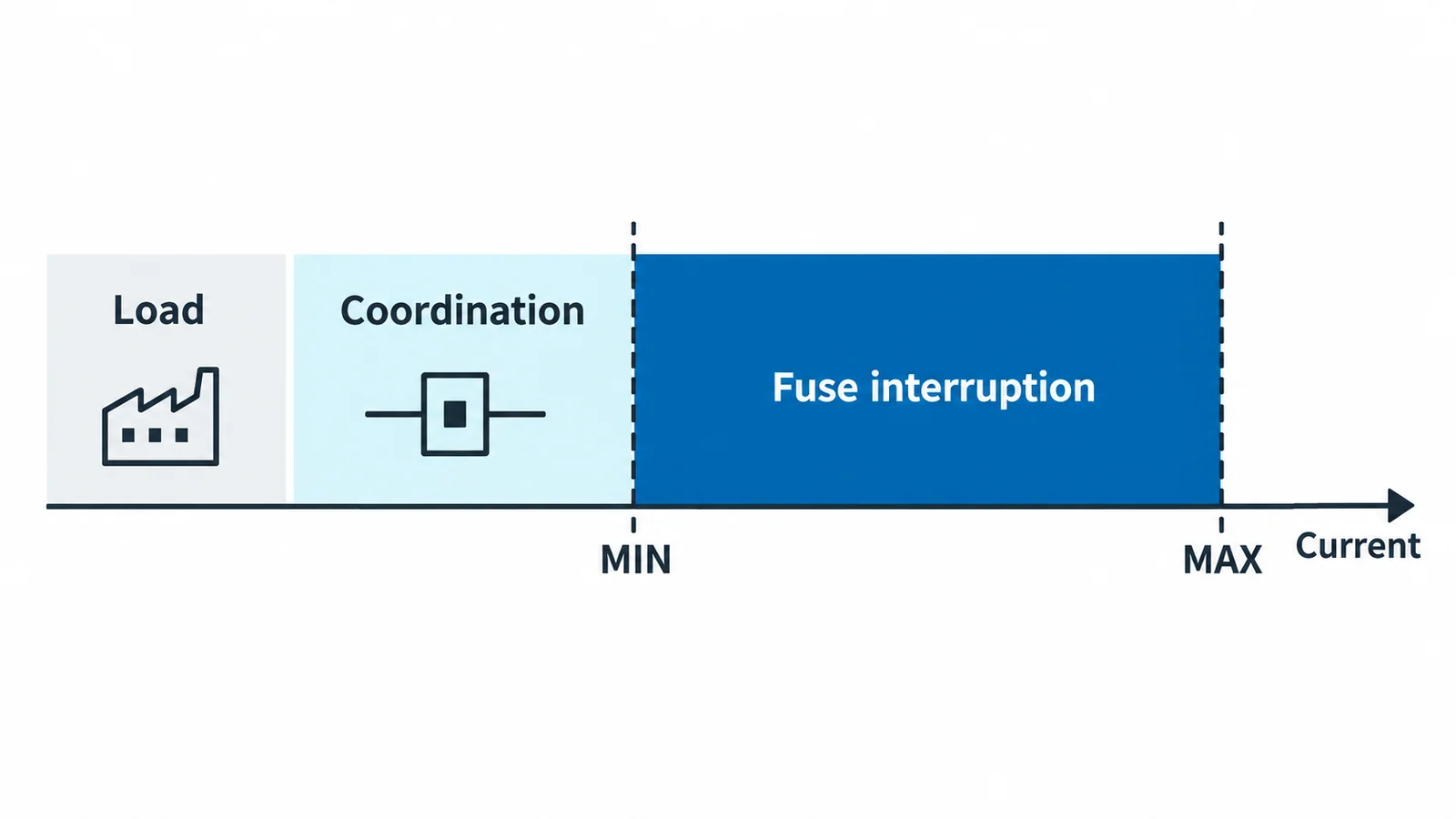
The exact lower boundary depends on the fuse-link class and declared characteristics. Do not infer one classification from another product’s catalog or quote a universal minimum breaking current. The standard’s edition and the link’s tested configuration matter.
Check the complete fault-current range
Begin with the network study: maximum and minimum prospective fault current at the fuse position, along with likely overload and transformer inrush conditions. Compare the entire current range with the fuse’s published characteristic and the adjacent protective devices. A high-current interrupting capability is only one end of the problem. At a lower current, the upstream device, associated switch or another protective function may need to clear the circuit. A coordination study must identify who operates and whether each device’s duty remains within its tested region.
For a transformer feeder, a fuse must avoid unintended operation on permissible energization and load transients yet protect against relevant faults within the chosen system arrangement. That is a project-specific TCC and equipment-duty exercise, not a rule to select a link by transformer kVA alone. The MCB versus fuse article discusses technology differences in a different, mainly low-voltage selection context; do not transfer its device ratings to MV fuses.
Check the surrounding assembly and service conditions
The fuse holder, switch, enclosure, striker linkage and mounting affect the application. IEC 62271-105:2021 covers AC switch-fuse combinations above 1 kV up to and including 52 kV as functional assemblies; a fuse-link test alone does not establish the full assembly’s making and breaking function. Review the approved combination, thermal conditions, ventilation, link dimensions and replacement instructions for the installed equipment.
Ambient temperature matters to current-carrying capability and may affect a fuse’s operating characteristic. The IEC catalog for the 2020 current-limiting fuse standard specifically notes clarified requirements for surroundings above 40 °C. That fact is not a license to apply a universal derating percentage: use the actual link’s documented condition and the assembly’s thermal assessment.
Five checks for a replacement fuse link
- Identify the installed fuse type, applicable product standard and required assembly compatibility.
- Verify rated voltage and insulation application against the actual system—not only the nominal label.
- Check rated current against continuous and expected transient duty under the installed thermal conditions.
- Compare maximum and minimum fault cases with the fuse’s breaking range and TCC, including coordination with other devices.
- Confirm dimensions, mounting, striker/indicator behavior and approved switch-fuse combination before substitution.
The output is a documented match between a particular link and a particular circuit/assembly. A fuse with the same physical size and ampere value is not automatically a safe replacement. For a reusable distinction between fuse and breaker specification language, see Medium-Voltage Circuit Breaker Ratings.