
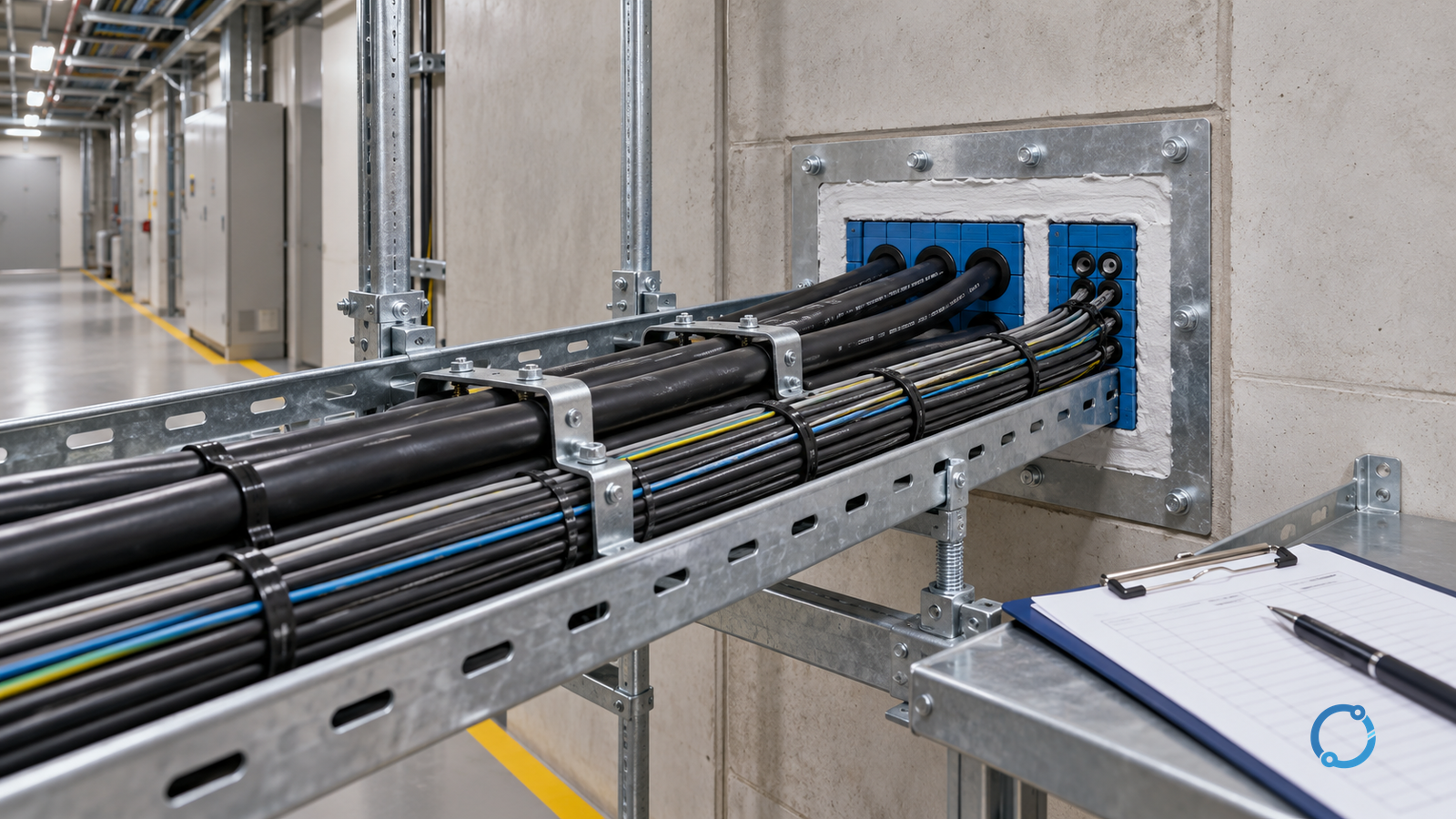
“Fire-rated cable” is an incomplete description. It does not say what hazard was tested, what performance was demonstrated or whether the installed route can maintain that performance.
Cable systems may be specified for several different fire-related properties:
- resistance to flame propagation;
- low smoke emission;
- limited corrosive or acid-gas emission;
- maintained circuit integrity for a stated period under a stated fire exposure;
- reduced heat release or other project-specific characteristics.
IEC 60332-1-2 addresses vertical flame propagation for a single insulated wire or cable under a defined test. IEC 60332-3-24 addresses flame propagation in vertically mounted bunched wires or cables, Category C. IEC 60754-1 addresses halogen acid gas evolved during combustion of cable materials. IEC 61034-2 addresses measurement of smoke density in a defined apparatus.
Each standard answers a different question. A cable that passes a single-cable flame test has not automatically demonstrated low smoke, low acid gas or fire-resistant circuit integrity. A test classification also does not prove that the complete installed route, support system and penetration assembly will perform as intended.
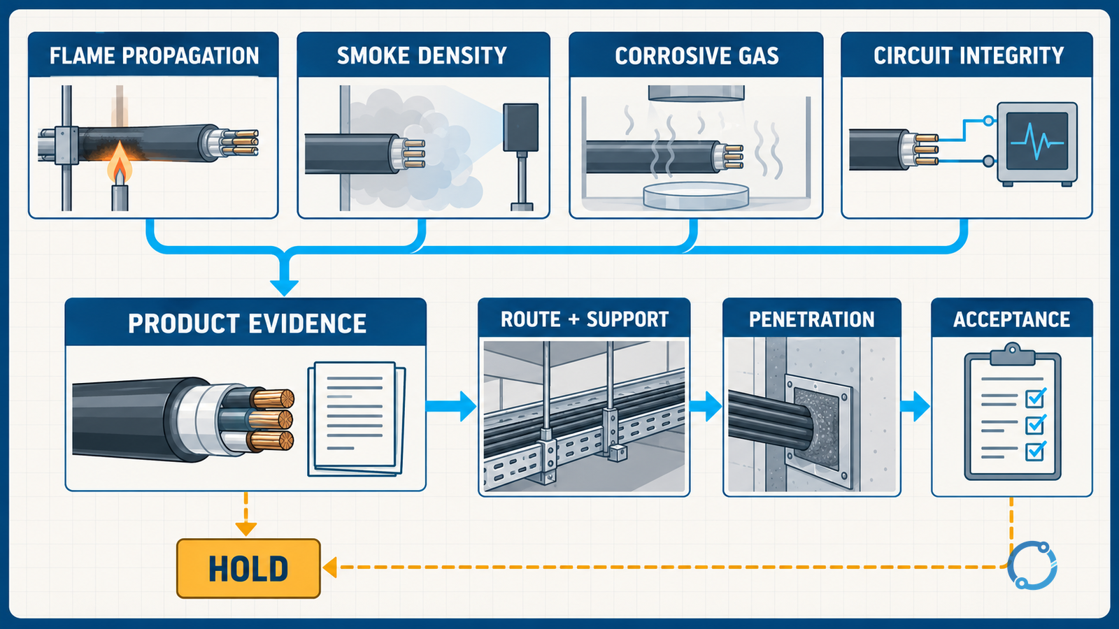
The project must connect four things:
- the fire objective;
- the exact product claim;
- the tested construction and installation conditions;
- the delivered and commissioned system.
When those four do not line up, the label on the drum can be correct while the installation is still unsuitable.
Define the fire objective first
A fire strategy may need to achieve different outcomes in different zones:
- limit flame travel along a cable route;
- reduce smoke obscuration in an occupied area;
- reduce corrosive damage to nearby equipment;
- preserve power or control for an evacuation, shutdown, firefighting or safety function;
- prevent fire from passing through a compartment boundary;
- support inspection and emergency response.
These are not synonyms. A cable selected to reduce flame propagation may still produce smoke. A low-smoke cable may not maintain circuit integrity. A fire-resistant cable may be suitable for a circuit only when its supports, termination, joints and penetration details are part of the tested installation.
Begin with a project fire matrix:
| Area or circuit | Required outcome | Design basis | Product evidence | Installation evidence |
|---|---|---|---|---|
| Normal route | Limit propagation | Route and occupancy risk | Test report/class | Tray fill and support |
| Occupied egress | Reduce smoke and gas risk | Fire strategy | Smoke/gas test | Route and compartmentation |
| Safety function | Maintain circuit integrity | Required duration and exposure | Fire-resistance system | Tested supports and details |
| Boundary crossing | Prevent spread | Compartment plan | Penetration system | As-built seal record |
The exact criteria belong to the project, local code and fire strategy. This table is a discipline for locating the requirement, not a universal national classification.
Four cable properties are not interchangeable
Flame propagation
Flame-propagation testing asks how fire develops and travels along a cable under a defined arrangement. A single-cable test and a bunched-cable test can produce different results because fuel load, airflow and proximity to other cables differ.
The construction matters. Insulation, sheath, bedding, fillers, tapes, armour and coatings all contribute to the combustible mass and the path available to flame. The same conductor and voltage rating can be offered in several constructions with different fire-test evidence.
Record:
- exact cable family and construction;
- conductor, insulation and sheath materials;
- armour and bedding;
- test standard and category;
- single versus bunched arrangement;
- test report identity;
- installation instructions and restrictions.
Do not translate “flame retardant” into “does not burn.” The useful claim is limited to the tested condition.
Smoke density
Smoke can obstruct egress, hide equipment and impair firefighting even when flame spread is limited. IEC 61034-2 uses a defined smoke-density measurement method. The result depends on the product construction and test arrangement.
Smoke performance is not a universal safety score. A low-smoke cable may still release heat and gases, and the building’s detection, ventilation and egress design remain part of the system. Ask whether the project requires smoke reduction in the specific route and whether the test method matches the specification.
Corrosive or acid gas
Combustion products can damage electronics, switchgear, motors and building systems even at a distance from the flame. IEC 60754-1 covers halogen acid gas evolved from cable materials. The test result does not by itself prove safe evacuation or fire resistance.
Check the complete cable construction, not only the outer sheath. Fillers and other components can affect gas emission. Confirm that the test report describes the same product configuration and that the project’s acceptance rules use the correct test family.
Circuit integrity
Circuit integrity is a different claim from flame propagation. It asks whether a cable or cable system continues to perform its intended function under a defined fire exposure for a defined period.
The performance may depend on:
- conductor and insulation system;
- sheath and barriers;
- support spacing and material;
- tested joint and termination details;
- cable routing;
- fire exposure and test arrangement;
- the complete cable-system classification.
A cable product that is flame retardant is not automatically fire resistant. A fire-resistant cable is not automatically suitable for every support, joint or route. Use the exact system evidence and installation instructions.
Construction matters before installation starts
The fire performance of a cable begins with the delivered construction. The project should preserve a clear link from specification to purchase order, drum label, test evidence and installed route.
Conductor and insulation
Conductor material and size establish current-carrying duty. Insulation contributes to electrical performance and may also influence fire behaviour. XLPE, PVC, EPR and other materials have different temperature and combustion characteristics; the presence of a particular insulation name does not establish a fire classification.
Sheath, bedding and fillers
The overall cable construction can change flame propagation, smoke and gas results. A low-smoke outer sheath does not guarantee low smoke from the complete cable if internal components contribute substantially.
Armour and metallic screens
Metallic layers can provide mechanical and electrical functions, but they also affect heat transfer, fault behaviour and fire exposure. Bonding and earthing must remain correct.
Fire barriers and tapes
Additional layers may be part of a product or installation system. Their position, continuity and termination detail matter. A loose tape in the store is not evidence that the completed cable has the required fire performance.
Installation can invalidate a product assumption
A fire test is performed under a specified arrangement. A project can change that arrangement through:
- excessive bunching or tray fill;
- poor support spacing;
- mixing cable constructions;
- sharp bends or mechanical damage;
- missing or non-compatible joints;
- open cable entries;
- unsealed or incorrectly sealed penetrations;
- routing a cable outside the assumed exposure zone;
- painting, coating or adding foreign material;
- changing the support system.
The product manufacturer’s instructions and the tested system details should define these limits. Do not derive a tray fill, support interval or fire-stop assembly from a generic article. Those values depend on standards, product and project design.
A stage-gated installation workflow
Gate 1: establish the fire strategy
Obtain the project fire plan, single-line and route drawings, zone boundaries, safety functions and local code requirements. Identify each route’s required fire outcome.
Release condition: every route has a documented objective, not only a cable product name.
Gate 2: specify the exact evidence
For each cable family, record:
- construction and part number;
- voltage and current rating;
- flame test method and class;
- smoke and gas evidence where required;
- fire-resistance system evidence where required;
- installation restrictions;
- termination and joint requirements;
- penetration or support compatibility.
Release condition: the specification, not the supplier’s general brochure, names the evidence required.
Gate 3: verify delivery
Compare the drum, reel and cable marking with the approved product. Check:
- manufacturer and product family;
- construction and sheath;
- voltage designation and core arrangement;
- test marks or traceability;
- batch or drum identity;
- certificate or report reference;
- storage condition and visible damage.
Release condition: the delivered item has a traceable identity and matches the specified evidence.
Gate 4: control the route
Before pulling, inspect:
- tray and ladder type;
- support spacing and condition;
- route radius;
- fill and bunching;
- separation from heat sources;
- compatibility with the cable;
- fire compartment boundaries;
- pulling force and lubrication.
Release condition: the installed geometry is within the product and project instructions.
Gate 5: inspect installation damage
After pulling and during termination, check:
- sheath cuts and abrasion;
- insulation damage;
- crushing or kinking;
- excessive bend;
- metallic layer damage;
- foreign material;
- conductor strand damage;
- moisture ingress.
A defect that affects insulation or sheath integrity should be assessed before the circuit is energised. A cosmetic repair that is not part of the approved cable system may leave the fire claim unverified.
Gate 6: verify supports and interfaces
The support system may influence both mechanical performance and fire response. Check:
- support material and coating;
- spacing and clamp type;
- cable movement and thermal expansion;
- earthing and bonding;
- metallic tray continuity;
- fire-stop interfaces;
- separation from other services.
Do not assume that a support system used in one fire test is acceptable for a different cable arrangement. Use the system evidence.
Gate 7: inspect penetrations and compartment boundaries
Fire performance at a wall, floor or shaft depends on the complete penetration system:
- cable type and size;
- number and arrangement of cables;
- sleeve and opening;
- sealant or module;
- backing material;
- installation instructions;
- label and inspection record;
- future allowance for cable changes.
A bare opening is not made safe by surrounding cable with an unspecified sealant. The penetration detail should be qualified for the actual arrangement and maintained if cables are added later.
Gate 8: test and hand over
Complete the normal electrical checks, plus the project’s fire-system verification:
- cable continuity and insulation resistance where applicable;
- bonding and earthing;
- support and tray inspection;
- penetration labels and records;
- fire-stop installation sign-off;
- cable schedule and as-built route;
- test report and certificate package;
- future maintenance access.
Release condition: the installed cable system can be traced from design requirement to product evidence to construction record.
What to put in the fire-performance package
A concise package should contain:
- route and fire-zone plan;
- specified cable family and construction;
- exact test evidence references;
- approved manufacturer installation instructions;
- delivery and drum traceability;
- pull and installation record;
- support and tray details;
- penetration system details;
- non-conformance and resolution;
- handover inspection and test sign-off.
This package lets the asset owner answer a future question such as: “Why was this cable accepted through the fire wall?” It also makes future modifications safer because the tested interfaces are visible.
Joints and terminations are part of the system boundary
Cable joints and terminations can introduce materials, interfaces and installation conditions that are not represented by a sample of the cable alone. When the project’s fire objective extends to a complete circuit, confirm whether the joint or termination is included in the applicable system evidence and whether its supports, clearances and enclosure details match the instructions.
A termination may be electrically correct yet still sit outside the fire strategy if it is installed in an unprotected location, through an unsealed entry or with a support arrangement that was not part of the tested system. Treat a change of termination, joint or sealing detail as a design change until it has been compared with the approved basis.
This does not mean that every joint needs a bespoke fire test. It means that the acceptance record should state the boundary of the evidence. If the project claims complete circuit integrity, the evidence should address the complete circuit. If the claim is limited to the cable product, do not extend it silently to joints, terminations, supports or penetrations.
Maintenance after handover can change the result
Fire performance can be undermined by later work that looks routine: adding cables to a full tray, removing a fire-stop module, replacing a clamp with a different material, painting a cable or leaving an inspection cover open. A handover record is useful only when the future change-control process knows which details support the original acceptance.
Label route sections and penetrations where the project requires it, retain approved arrangements and require review before the installed population or support system changes. During maintenance, inspect the interfaces as well as the cable. A clean cable with a disturbed penetration is not the same accepted system that was handed over.
Common misunderstandings
“Low smoke means it will not burn.”
No. Smoke measurement is a separate property. It describes a defined combustion test, not non-combustibility or fire resistance.
“The cable is tested, so the installation is approved.”
No. The product test may not cover the support, bunching, penetration or circuit configuration installed on site.
“Fire-resistant cable is the same as flame-retardant cable.”
No. One concerns maintained function under a fire exposure; the other concerns flame propagation under a defined test. The exact terms and test basis must be checked.
“A fire-stop label proves the penetration is correct.”
No. The label should be supported by an installed arrangement that matches the tested system and the current cable inventory.
“A higher class is always the best answer.”
Not necessarily. The correct requirement depends on the fire strategy, the circuit function, the installed arrangement and the local code. A higher classification can be irrelevant if the actual installation falls outside the product’s tested conditions.
Worked acceptance case
An engineer specifies a cable for a route that crosses an occupied building and continues through a fire compartment.
The requirement includes:
- limited flame propagation along the tray;
- low smoke in the occupied route;
- low acid-gas emission for equipment protection;
- maintained circuit integrity for a safety function;
- sealed compartment penetration.
One proposal provides test evidence for flame propagation and low smoke, but no system evidence for circuit integrity. It also proposes a generic sealant for the penetration.
The correct decision is not to accept the proposal because two boxes are ticked. The design is still open:
- the circuit-integrity requirement is unsupported;
- the penetration system is not shown to match the installed cable arrangement;
- support and tray details are not verified against the fire system;
- the future cable-change policy is undefined.
The engineer should either select a qualified system or return the design for additional evidence. The accepted package must link every property to a real route or system requirement.
Review questions for a supplier or designer
Use these questions to make the comparison specific:
- Which exact test standard and class support each fire claim?
- Does the report cover the full cable construction?
- Is the test for a single cable or a bunched arrangement?
- What support, tray and bending conditions were used?
- What are the product restrictions for group installation?
- Does the fire-resistance claim cover a complete circuit system or only the cable?
- Are joints and terminations included?
- What penetration system is compatible?
- What evidence is required for maintenance or later modifications?
- Which local code or fire-engineering requirement decides acceptance?
A supplier response that cannot separate these points may still be useful commercially, but it is not a technical approval argument.
Final rule
Cable fire performance is a chain:
specified fire objective → exact product construction → applicable test evidence → qualified route and support details → verified installation → handover record
Break the chain at any point and the label becomes an unverified assumption. Treat flame propagation, smoke, corrosive gas and circuit integrity as separate claims. Verify that the installed route, penetration and protection strategy match the evidence. That is how a fire-performance specification becomes a controlled electrical installation rather than a collection of catalogue phrases.
For related cable context, read MV cable insulation types, LV cable terminations, cable sizing for circuit breakers and feeders and MV cable termination stress control and creepage failures.
Sources
- IEC, IEC 60332-1-2:2024 Tests on electric and optical fibre cables under fire conditions – Part 1-2: Test for vertical flame propagation for a single insulated wire or cable – Procedure for 1 kW pre-mixed flame.
- IEC, IEC 60332-3-24:2018 Tests on electric and optical fibre cables under fire conditions – Part 3-24: Test for vertical flame spread of vertically-mounted bunched wires or cables – Category C.
- IEC, IEC 60754-1:2019 Test on gases evolved during combustion of materials from cables – Part 1: Determination of the halogen acid gas content.
- IEC, IEC 61034-2:2025 Measurement of smoke density of cables burning under defined conditions – Part 2: Test procedure and requirements.