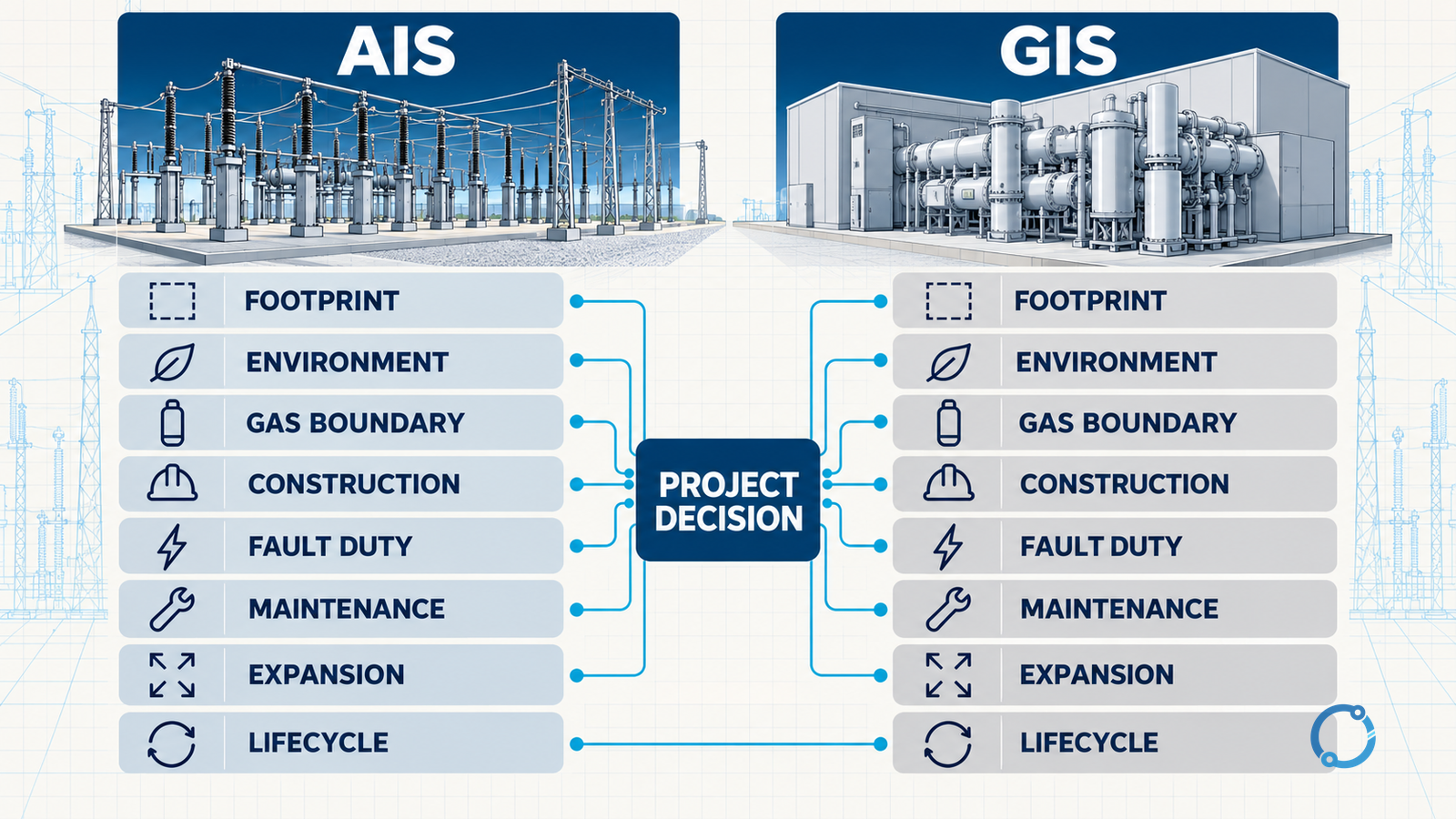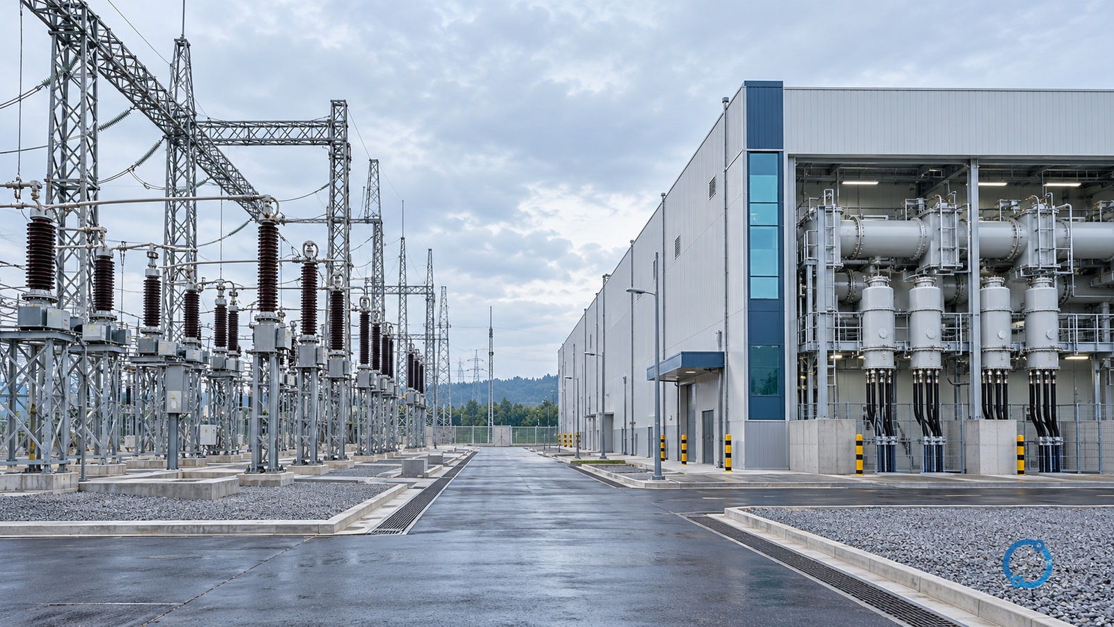
Air-insulated switchgear and gas-insulated switchgear are often compared as if the decision were a contest between two product types. In a substation, the real choice is an architecture. It determines what occupies land, how clearances are arranged, how the primary circuit is enclosed, how maintenance access is organised, how construction interfaces are sequenced and what the asset owner must manage for decades.
AIS uses air as the principal insulation medium around exposed or separately enclosed high-voltage equipment. GIS places the primary conductors, switching devices and related components inside metal enclosures with an insulating gas system. Neither description alone tells you which station will be best.
IEC 62271-1 supplies common specifications for high-voltage switchgear and controlgear. IEC 62271-203 specifically covers gas-insulated metal-enclosed switchgear for rated voltages above 52 kV. Those documents help define the equipment. They do not substitute for a project comparison of site constraints, reliability requirements, constructability, operating strategy and lifecycle cost.
The practical decision is:
Which station architecture can meet the required electrical duty and operating policy with the most defensible combination of footprint, environmental performance, constructability, maintainability, expansion and lifecycle evidence?
That question has no universal answer. The method for examining it does.
First define the station boundary
Before comparing AIS and GIS, define what is included in the scope. A paper comparison can accidentally compare a GIS bay enclosure against only the visible AIS switchyard equipment while omitting civil works, cable sealing ends, protection buildings, access roads, earthing and site preparation.
Record the complete scope:
- incoming and outgoing circuits;
- voltage levels and transformation;
- busbar arrangement and redundancy;
- circuit breakers, disconnectors and earthing switches;
- current and voltage transformers;
- surge arresters and cable or line interfaces;
- protection, control, auxiliary supply and communications;
- station earthing and lightning protection;
- buildings, roads, drainage and environmental controls;
- construction interfaces and future bays;
- operations and maintenance resources.
The architecture comparison must be symmetric. Include the same functions on both sides, even if they occupy different physical forms.
Define the project drivers before the technology
A technology recommendation becomes arbitrary unless the project records its priorities. Useful drivers include:
- available land and site geometry;
- seismic, wind, flood and pollution conditions;
- temperature, humidity, salt and industrial contamination;
- proximity to public roads, buildings or sensitive environments;
- required availability and outage strategy;
- expected expansion sequence and spare-bay provision;
- connection voltage and fault level;
- transport and crane access;
- skill base for operation and maintenance;
- gas management and end-of-life obligations;
- construction schedule and commissioning constraints;
- total lifecycle cost and financing assumptions.
Write these as weighted requirements only after the engineering constraints are known. A scoring model cannot hide a site that lacks the necessary land or a design that cannot be maintained with available personnel.
AIS: the station is the insulation arrangement
In an air-insulated substation, phase spacing, phase-to-earth clearance, support insulators, conductor geometry and environmental exposure are central to the layout. The switchyard is legible in three dimensions. Personnel can often see the physical connection and the location of major equipment.
That visibility is valuable. It also means the design must control pollution, wind, wildlife, vegetation, lightning and unauthorized access. The performance of the station depends on the complete arrangement, not only the individual breakers and disconnectors.
AIS strengths
- Layout and primary connections may be easier to inspect visually.
- Equipment can be maintained or replaced in discrete sections, subject to outage planning.
- Clearances and component positions provide a direct relationship between drawings and the yard.
- Expansion can be straightforward when land, busbars and protection are planned for it.
- The equipment count and site interfaces are often easier to identify at an early stage.
AIS constraints
- Clearance requirements can increase footprint, fencing and land preparation.
- Pollution, salt, dust, humidity and snow can affect external insulation.
- Wind and seismic loads must be resolved through supports, conductors and foundations.
- Outdoor exposure increases the importance of coatings, seals, drainage and wildlife mitigation.
- More of the station is accessible for inspection, but more of it also requires inspection.
These are architectural consequences, not an assertion that AIS is less reliable. Actual performance depends on design margins, manufacturing, construction quality and operating practice.
GIS: the station is a managed gas boundary
GIS compresses the primary circuit into metal enclosures. The insulating and switching environment becomes an engineered gas volume divided into compartments, with bushings or cable terminations at the interfaces to the outside system.
IEC 62271-203 addresses metal-enclosed gas-insulated switchgear above 52 kV. The standard is important for understanding the product context, but it does not determine the complete substation architecture. The project must still address buildings, ventilation, gas handling, earthing, seismic supports, transport, bushings, control and protection.
GIS strengths
- A compact footprint can release land for other uses.
- Enclosure and controlled internal conditions can reduce exposure to external pollution.
- The primary circuit can be factory-integrated into modules, reducing some site assembly work.
- Condition monitoring and compartment-level diagnostics can support planned maintenance.
- The visual and access boundary can be clearly defined around enclosed bays.
GIS constraints
- Gas compartments require specified gas quality, pressure monitoring, handling and leak management.
- A fault or internal arc can involve access, gas removal, compartment isolation and specialist recovery.
- Internal defects are not inspected by ordinary visual walk-around.
- Factory assembly, transport, lifting and site alignment require disciplined interfaces.
- Expansion requires spare bays, bus extensions and clear enclosure interfaces.
- End-of-life gas recovery and equipment disposal become part of the asset obligation.
The phrase “maintenance-free” should be avoided. GIS may require less routine external inspection for some components, but it still needs monitoring, protection, gas checks, exercise or operation where specified, auxiliary-system maintenance and intervention planning.
Eight dimensions that make the comparison useful
1. Land and layout
Compare the full land take, not only the switchgear footprint. Include:
- phase and earth clearances;
- maintenance access;
- crane and delivery zones;
- control buildings;
- cable sealing-end structures;
- future bays and bus extensions;
- roads, drainage, fire separation and security.
GIS often offers a smaller electrical footprint, but the advantage is not automatic if the design requires a large building, gas store or difficult cable interface. AIS may use more land while offering a simpler direct access geometry. The design team should draw both options to the same scope and scale.
2. Environment
Map the site conditions:
- pollution and salt;
- humidity and condensation;
- dust, sand or industrial emissions;
- wind, snow and seismic loading;
- flood level and drainage;
- wildlife exposure;
- ambient temperature;
- corrosive atmosphere.
GIS can reduce primary-circuit exposure, but external bushings, cable terminations and buildings remain exposed. AIS makes clearance and insulation visible but requires pollution and environmental management. Neither architecture removes the need for project-specific insulation coordination.
3. Gas and enclosure management
For GIS, define:
- gas type and compartment boundaries;
- filling and evacuation procedures;
- pressure and density monitoring;
- leak detection and alarm limits;
- spare-gas storage;
- recovery equipment;
- training and competent-person requirements;
- reporting and environmental obligations;
- end-of-life recovery.
Gas management is not a maintenance footnote. It affects layout, ventilation, access, emergency response and lifecycle cost. It must be included in the architecture comparison from the beginning.
For AIS, the corresponding environmental management focuses on air clearances, insulation pollution, exposed surfaces, wildlife, windborne material and water drainage. The two lists are different, but neither is empty.
4. Constructability and commissioning
Compare:
- factory integration versus site assembly;
- module transport and lifting;
- foundation tolerance;
- civil-work interfaces;
- cable and line connection;
- high-voltage testing needs;
- gas filling and pressure stabilisation;
- protection and interlock testing;
- access during construction.
GIS can move much of the primary-circuit assembly into a controlled factory environment, but it also creates exacting interfaces for foundations, alignment and cleanliness. AIS spreads more work across the yard, making scheduling and weather management important. Claims about schedule should come from a project-specific construction plan.
5. Electrical and fault duty
Both options must meet the same system requirements:
- rated voltage and insulation level;
- continuous current;
- short-circuit breaking and making duty;
- short-time withstand;
- switching overvoltage;
- capacitive or inductive switching duty where relevant;
- earthing and touch-voltage performance;
- surge protection.
The architecture does not exempt a product from these checks. Compare the ratings on the same basis and include outgoing cable or overhead-line effects. For example, a compact GIS building can change the cable route and surge environment; an AIS yard can change the exposure of bushings and the lightning-protection arrangement.
6. Condition visibility and maintenance
Compare what can be observed, how a fault is localised and what intervention is needed.
AIS generally offers more direct visual access to structural and insulation condition, but observation is not the same as diagnosis. GIS can provide pressure, density and diagnostic signals, but a sensor indication is not proof that the internal condition is sound.
Define:
- routine inspection tasks;
- condition-monitoring strategy;
- alarm and trip response;
- spares strategy;
- access to compartments;
- gas recovery and refilling;
- outage duration assumptions;
- competency and tooling.
Do not score GIS as superior because it is enclosed or AIS as superior because it is visible. Score the actual maintenance plan and the asset owner’s capability to execute it.
7. Outage and expansion strategy
The station is rarely finished on day one. A useful comparison tests:
- adding a feeder without taking the main bus out of service;
- replacing a breaker or instrument transformer;
- extending the bus;
- separating protection and auxiliary systems;
- maintaining one section while another remains available;
- moving future equipment through the site.
GIS typically needs explicit spare bays and interfaces to preserve expansion options. AIS may make future geometry visible and incremental, but land reservation and outage planning are still required. The decision should be tied to a staged single-line diagram, not a generic claim that one architecture is easier to expand.
8. Lifecycle cost and risk
A lifecycle model should include:
- initial equipment and civil works;
- design and engineering;
- transport, installation and commissioning;
- buildings and environmental control;
- protection and monitoring;
- routine operation;
- planned and corrective maintenance;
- gas supply, leakage and recovery;
- spare parts and specialist support;
- outage consequences;
- replacement and disposal.
Use actual quotations, labour rates, outage costs and energy or gas data where available. If a number is not known, show it as an assumption rather than hiding it in a single total. A design with a lower initial price can have a higher lifecycle cost, and a higher initial price can be justified by a smaller footprint or better outage performance. Neither outcome should be asserted without the model.
Comparison table: use it as a prompt, not a score
| Dimension | AIS question | GIS question | Evidence needed |
|---|---|---|---|
| Footprint | Can the site accommodate clearance and access? | Does the smaller primary footprint offset building and gas needs? | Scaled layout and land plan |
| Environment | Are external insulation and structures protected? | Are bushings, building and gas boundaries protected? | Site data and environmental design |
| Gas | No primary gas compartment, but what other environmental controls apply? | What gas volume, monitoring and recovery are required? | Gas management plan |
| Construction | Can yard work be sequenced safely? | Can modules be delivered and aligned accurately? | Construction method statement |
| Fault duty | Are clearances and supports adequate? | Are enclosure, bus and gas systems rated? | Equipment and system study |
| Maintenance | Can condition be inspected and work isolated? | Can condition be monitored and compartments recovered? | Asset-management plan |
| Expansion | Is land and bus extension available? | Are spare bays and bus interfaces provided? | Future single-line diagrams |
| Lifecycle | What are land, labour, outage and replacement costs? | What are building, gas, specialist and outage costs? | Project cost model |
The table prevents one technology from being judged only on its strongest dimension. It also exposes missing data early.
AIS and GIS can coexist
Many substations use a hybrid arrangement: AIS equipment outdoors, GIS bays in a building, or GIS for selected high-value sections. The decision is not always binary.
Hybrid designs can capture footprint or interface benefits, but they add transition boundaries. The review should then cover:
- cable or busbar interfaces between technologies;
- earthing and surge coordination;
- protection-zone boundaries;
- maintenance responsibility;
- spare-parts strategy;
- expansion at the transition;
- testing and commissioning interfaces.
A hybrid architecture is not automatically easier because it uses familiar components in a new arrangement. It needs the same single-line-diagram and asset-ownership discipline.
Civil and building design are part of the electrical architecture
An AIS-versus-GIS comparison remains incomplete if it ends at the equipment list. The station’s electrical performance depends on foundations, cable trenches, drainage, roads, buildings, earthing, lightning protection, ventilation and fire strategy. These are not secondary construction details; they determine whether the selected equipment can be installed, inspected, maintained and expanded.
For AIS, support structures and foundations must resolve conductor loads, wind and seismic effects. Clearance areas must remain usable during maintenance. For GIS, building tolerances, lifting paths, ventilation, gas handling and cable or line interfaces can dominate the constructability review.
Ask the civil, structural, electrical and commissioning teams to review the same layout at the same time. A station that has a compact primary circuit but no safe equipment-moving path has not realized its footprint advantage. A station that has ample land but cannot isolate a future bay has not protected its expansion option.
Common comparisons that mislead
Several statements sound useful but are too general:
- “GIS is always more reliable.”
- “AIS is always easier to maintain.”
- “GIS always saves land.”
- “AIS always has lower lifecycle cost.”
- “A sealed system requires no maintenance.”
- “Visible equipment is easier to diagnose.”
Each statement hides the project conditions that control the answer. Reliability is a function of design, manufacture, installation, operating environment, protection and maintenance. Maintenance depends on access, skills, spares and outage rules. Land saving depends on the complete station layout. Lifecycle cost depends on the financial and operational model.
Replace those slogans with evidence:
- a layout drawing at the same scope;
- gas and environmental plan;
- site pollution and climate data;
- product and system ratings;
- construction method;
- maintenance and outage plan;
- spares and competency plan;
- cost model with transparent assumptions.
The decision record
A project should not end with the sentence “We selected GIS because it is compact.” It should record:
- the station’s required functions and redundancy;
- the land and environmental constraints;
- the comparison scope and assumptions;
- the AIS and GIS layouts;
- the fault, insulation and switching duties;
- the construction and commissioning approach;
- the operations, maintenance and gas-management strategy;
- the expansion and replacement plan;
- the lifecycle cost model;
- the unresolved risks and decision owner.
That record allows the design to be reviewed when the site changes, when a future bay is added or when the asset-management strategy evolves.
Final selection rule
Choose AIS when the site, environment and operating model make an air-insulated station with visible clearances and defined outdoor maintenance the better total solution. Choose GIS when a controlled enclosure, compact layout and managed gas system provide a stronger project case. Choose a hybrid when the interfaces are documented and the combined architecture performs better than either single form.
In every case, selection should follow the same hierarchy: define the station, define the system duty, compare equal scopes, test the physical and environmental constraints, verify construction and lifecycle implications, then obtain approval. The technology label comes after the evidence, not before it.
For related background, read distribution substation basics, GIS bay maintenance, isolation and restoration, medium-voltage switchgear commissioning and release and SF6 versus vacuum circuit breakers.