
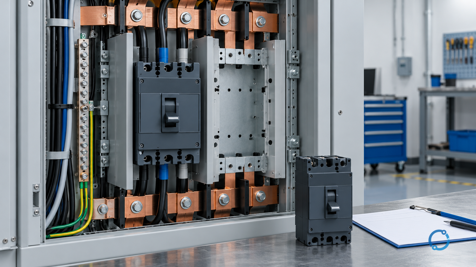
A circuit breaker that fits the vacant opening is not automatically an acceptable replacement. Two devices can share the same pole count, nominal current and physical width while differing in voltage rating, interrupting capacity, trip curve, terminals, accessories, enclosure approval or the conditions under which the original assembly was evaluated.
The confusion often appears around the words specified, classified, listed and compatible. These words do not form a simple quality ranking. They describe different pieces of evidence:
- Specified usually means that a project, enclosure, panelboard, switchboard or instruction identifies a product or set of conditions for use.
- Classified describes a product-evaluation category and the boundaries of that evaluation.
- Listed describes a product that appears in an appropriate certification or listing record for its evaluated scope.
- Compatible is a conclusion about a defined application, not a synonym for “looks similar” or “has the same amp rating.”
The practical question is therefore not “Is a classified breaker better than a specified one?” It is:
What was evaluated, for what use, in what enclosure, under which ratings and with what documented approval?
A replacement should remain on hold until those answers are traceable.
Start with the device’s actual function
The first distinction is functional. A device may be intended as a branch-circuit breaker, a feeder breaker, a service disconnecting means, a supplementary protector, a motor-circuit protector or a switch-disconnector. Those roles can overlap in some installations and diverge sharply in others.
UL 489 is the product outline commonly associated with molded-case circuit breakers, molded-case switches and circuit-breaker enclosures for service, feeder and branch-circuit applications. UL 1077 is associated with supplementary protectors, which provide supplementary overcurrent protection but are not automatically substitutes for branch-circuit breakers. The exact product category must be read from the current standard, certificate and listing record rather than inferred from appearance.
This distinction matters because the word “breaker” can refer to several product families. A supplementary protector may be suitable inside a listed assembly for a specific supplementary function, but that does not prove it can replace a branch-circuit breaker. Conversely, a branch-circuit breaker is not automatically correct for every motor, DC, photovoltaic or direct-current-control application.
Record the following before comparing candidates:
- The protected circuit and load type.
- Whether the device serves as service, feeder, branch-circuit or supplementary protection.
- The nominal system voltage and number of poles.
- The available fault current at the installation point.
- The trip characteristic and coordination role.
- Whether switching, isolation or emergency functions are assigned to the device.
- Any series rating, selective coordination or motor-protection design that depends on the original device.
If the function cannot be identified from drawings, labels and the existing assembly, stop. A breaker selection cannot be repaired with a longer catalogue search.
What “specified” means in a real installation
A specified breaker is tied to a defined application. That application may be a panelboard type, switchboard section, motor control centre, equipment assembly or a project specification. The requirement can appear in several places:
- the equipment nameplate or directory;
- the enclosure instructions and marking;
- the approved construction drawing;
- the short-circuit and coordination study;
- the panel heater, terminal and accessory schedule;
- the specification section used for procurement;
- a field evaluation or authority approval.
A breaker may be specified by manufacturer and catalogue number because the physical interface, heat dissipation, terminal spacing, trip unit or accessories were included in the assembly evaluation. A seemingly equivalent breaker from another family may not reproduce that evaluated assembly even when the external dimensions are close.
This is why “same size” is weak evidence. The useful dimensions include:
- pole spacing and busbar interface;
- terminal depth and cable-bending space;
- mounting rail or fixed pattern;
- handle, door and interlock geometry;
- neutral and earth accessories;
- shunt trip, undervoltage trip and auxiliary contacts;
- wire range and terminal material;
- ventilation and adjacent-device heat;
- labels, barriers and arc-flash boundaries;
- torque access and maintenance clearance.
A product can pass every individual rating check and still be unacceptable because the enclosure was not evaluated for that combination.
What “classified” means
Classified is an evaluation statement. It says that a product has been assessed against a defined classification or product-evaluation basis for certain uses. It does not mean that the product may be installed anywhere, at any voltage or in any panel.
In discussions of panelboard replacement, the reader may encounter a breaker described as classified for use in equipment from another manufacturer. That wording requires careful reading. The key questions are:
- Which replacement breaker product and revision was evaluated?
- Which enclosure or equipment families were included?
- Which ratings, accessories and terminal arrangements were included?
- What installation instructions apply?
- Is the existing panel label consistent with that use?
- Does the applicable electrical code allow the substitution?
- Has the authority responsible for the installation accepted the basis?
A classification report or database entry is evidence for the assessment it records. It is not a general interchangeability certificate.
Equally, a product marked “listed” is not automatically plug-compatible with an existing panel. The listing scope may cover the breaker as a standalone product, while the panel enclosure may require a particular breaker series, accessory set or field-installation instruction.
Do not collapse four different approval questions
The substitution decision becomes clearer when four questions remain separate.
Product identity
Does the proposed device have the correct product family, voltage class, current rating, poles, trip type and interrupting rating? Product identity is established from the current label, certificate or listing record, not a sales description.
Assembly compatibility
Was the proposed device evaluated or accepted for the enclosure, busbar, deadfront, door, handle, terminal and accessories in this installation? Assembly compatibility can be narrower than product compatibility.
System duty
Does the replacement preserve the required fault interruption, protection and coordination? Available fault current, clearing time and upstream/downstream selectivity matter. A higher interrupting rating is not automatically a substitute for an unchanged protection setting or trip characteristic.
Local approval
Does the applicable code, project specification and authority having jurisdiction accept the basis? Local approval is a separate gate and should not be assumed from an online statement.
All four answers must align before the replacement is released.
The breaker substitution matrix
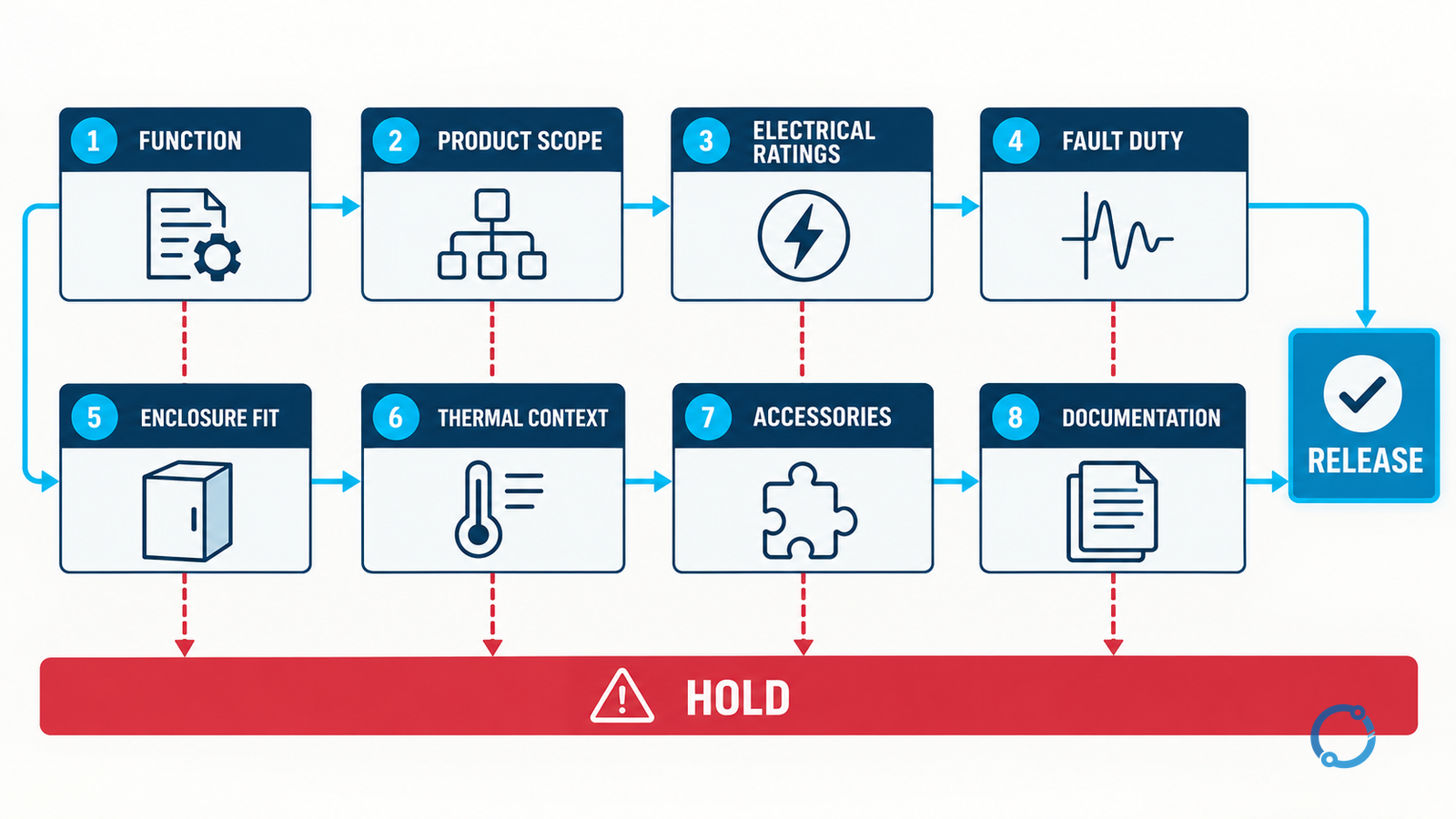
Use the following eight-row matrix as the record for a candidate substitution.
| Gate | Evidence to record | Release condition | Common failure |
|---|---|---|---|
| Function | Circuit diagram, panel schedule, service/feeder/branch role | The device has the same defined protection function | Treating all overcurrent devices as equivalent |
| Product scope | Current standard and listing/classification record | The product category matches the intended use | Reading a catalogue family name as a certification |
| Electrical ratings | Voltage, current, poles, frequency, interruption and trip data | Every rating is adequate for the application | Comparing only the handle rating |
| Fault coordination | Available fault, upstream/downstream settings, series-rating basis | Interruption and coordination remain valid | Assuming a higher interrupting rating is enough |
| Enclosure fit | Panel type, busbar, deadfront, rail, door and terminal schedules | The assembly is evaluated or approved for the item | Matching width but not terminal or accessory geometry |
| Thermal context | Adjacent devices, cables, grouping and ventilation | Grouped operation and heat conditions remain acceptable | Ignoring heat from a new breaker family |
| Accessories | Neutral, shunt trip, auxiliary contacts, handle and locks | Accessories and circuit functions are preserved | Losing a monitoring or isolation function |
| Documentation | Drawings, labels, instructions, approval and as-built record | The change is traceable and authorised | Relying on an email or a catalogue note |
This table is not a selection template for every jurisdiction. It is a discipline for preventing a weak inference from becoming an energised system change.
The apparent-equivalence trap
The most common mistakes are easy to describe:
- The old breaker has a 100 A frame, so the replacement must be 100 A.
- The replacement has a higher interrupting rating, so it must be safer.
- The new breaker has the same panel width, so the door and deadfront will fit.
- The supplier lists a “compatible” accessory, so the complete combination is approved.
- The original breaker is obsolete, so a similar current product is the closest available option.
- A local electrician has used the replacement elsewhere, so it must work here.
Each statement omits the conditions that make an electrical substitution acceptable. The 100 A label may describe a frame size rather than the trip setting. The higher interrupting rating may not match the existing trip curve or busbar assembly. The enclosure may require a barrier or label that was omitted from the comparison. A similar field installation may have a different panel revision, cable direction or protection scheme.
The replacement process has to recover the missing evidence, not choose the most confident-sounding supplier statement.
A safe replacement workflow
1. Isolate and identify
De-energise and secure the circuit using the site’s approved lockout, tagout and verification procedure. Only qualified persons should open the equipment or perform electrical tests. Record the panel, section, breaker position, device label, trip unit, accessories and visible condition before removal.
2. Recover the original basis
Collect the panel schedule, single-line diagram, equipment label, manufacturer instructions, breaker label, torque information, coordination study and any prior modification records. Photograph the mounting and terminal arrangement. Note heat discolouration, loose conductors, damaged insulation and corrosion without touching energised parts.
3. Define the replacement duty
State the nominal voltage, load current, available fault current, earthing arrangement, ambient conditions, trip characteristic and required switching functions. Verify whether the device is part of a series-rated combination, arc-flash boundary or selective-coordination scheme.
4. Assemble candidate evidence
For each candidate, obtain the exact product standard scope, certificate or listing record, installation instructions, rating table, terminal data and accessory schedule. Treat a vendor cross-reference as a prompt for investigation, not the final approval.
5. Test the eight gates
Complete the matrix. Mark each row supported, open or rejected. Do not average a missing row against five good ones. A missing terminal schedule or unknown panel revision is a stop condition because the combined assembly is not yet demonstrated.
6. Review the thermal and fault case
Confirm that grouped operation, cable size, terminal material, breaker spacing and enclosure temperature remain acceptable. Recalculate or recheck the fault current and coordination basis if the replacement changes trip technology, clearing time or internal heat. Do not use a generic derating factor without the applicable product or study basis.
7. Install only after release
Use the approved instructions for conductor preparation, torque, phase sequence, neutral and earthing, barriers and labels. Verify that the breaker is in the intended position and that all unused openings and accessories are handled as required. Replace covers and guard plates before re-energisation.
8. Validate and record
Perform the site’s approved mechanical, insulation, continuity and functional checks. Verify trip indication, accessory operation, door interlock and labelling. Record the exact replacement part, serial or batch information, settings, torque evidence, test results, approvals and revision of the panel documents.
Worked boundary case: the correct rating, wrong assembly
Consider a three-phase distribution panel with a failed 63 A feeder breaker. The proposed replacement has:
- the same three-pole configuration;
- a 63 A rating;
- a higher short-circuit interrupting rating;
- a matching voltage class;
- an apparently identical front width.
The comparison still is not complete. The existing panel uses a busbar comb, a particular terminal shroud and a neutral accessory within the same compartment. The replacement accepts a different conductor range and has a different thermal spacing. Its handle protrudes into the door mechanism, and the existing label names a specific breaker series.
At that point, the electrical ratings may look suitable, but the assembly evidence is incomplete. The correct action is to hold the change until the enclosure manufacturer, responsible engineer or other authorised body confirms the combination, or select a product that the assembly documentation explicitly permits.
This example also shows why “higher interrupting rating” can distract from more important facts. The fault-duty improvement does not repair a door clearance, terminal mismatch or undocumented thermal change.
When to stop
Stop and escalate the decision when any of the following remains unresolved:
- the original breaker’s function cannot be established;
- the panel label or instructions contradict the proposed product;
- the enclosure family or revision is unknown;
- the available fault current is unknown and cannot be bounded;
- the replacement changes the neutral, earth, shunt-trip or interlock arrangement;
- the terminal or torque data are unavailable;
- the device would be used outside its voltage, DC, frequency or environmental rating;
- the proposed combination has no acceptable documentation;
- the applicable code or authority requires a product or field evaluation that is not present.
An unresolved row is not a reason to rely on “engineering judgement” in secret. It is a reason to make the missing assumption visible and obtain the authority to resolve it.
What a replacement record should contain
A concise record is more useful than a supplier screenshot. It should contain:
- Installation identifier and circuit description.
- Original device identity and removal reason.
- Rated voltage, current, poles, interruption and trip data.
- Available fault current and coordination assumptions.
- Proposed replacement product identity and documentation references.
- Complete enclosure and accessory compatibility evidence.
- Thermal and grouping conditions.
- Local code and authority review.
- Installation instructions and torque evidence.
- Functional test results and final as-built update.
The record allows another engineer to review the decision later. It also makes clear whether the replacement is a like-for-like repair, an approved modification or an unverified experiment.
A practical rule for buyers and maintainers
When a breaker becomes obsolete, the fastest quotation is rarely the safest decision. Ask for:
- the exact product family and revision;
- the applicable standard or certification scope;
- the panel compatibility basis;
- the voltage, current, poles and interrupting rating;
- the terminal and accessory schedule;
- the installation instructions;
- the fault and coordination implications;
- availability of a technical rather than sales-only response.
A supplier who understands the distinction will usually distinguish “the breaker is classified” from “this complete panel installation is approved.” That is the level of clarity required before a replacement can be released.
Change control is part of the replacement
A breaker replacement should leave the equipment easier to maintain, not merely easier to start. Once the device is installed, update the panel schedule, single-line diagram, arc-flash label where its assumptions changed, coordination-study model, spare-parts record and maintenance history. Keep the approved compatibility evidence with the asset record.
That step matters when the next failure occurs. A future technician may otherwise see a device that fits the opening and assume it was part of the original design. The record should show that the replacement was a reviewed change, identify who approved it and distinguish supplied manufacturer data from a completed engineering assessment.
If the substitution remains provisional, do not convert a working circuit into a permanent approved design by leaving it in service. Define the temporary basis, monitoring, expiry and the action needed to replace it with a fully supported configuration.
Final decision rule
Do not ask whether two breakers are “basically the same.” Ask whether the proposed product, enclosure, ratings, fault duty, thermal context, accessories, installation instructions and authority approval are all documented for this specific application.
If every gate is supported, the replacement can be treated as an approved engineering change. If any gate is open, the correct state is HOLD until the evidence is complete. That distinction is more valuable than a universal cross-reference table, because it remains true as products, standards and panel revisions change.
For the surrounding specification and protection framework, compare low-voltage protective-device ratings and compatibility, low-voltage circuit-breaker selectivity and ANSI circuit-breaker rating comparison. Teams specifying monitoring or remote operation can also review intelligent breakers in switchgear specification.
Sources
- UL Solutions, UL 489 outline of investigation for molded-case circuit breakers.
- UL Solutions, UL 1077 outline of investigation for supplementary protectors.
- UL Solutions, UL Product iQ and certification records.
- NFPA, National Electrical Code / NFPA 70.