
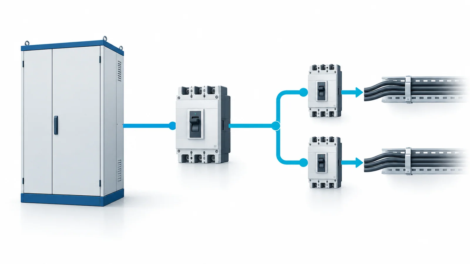
Selectivity means a downstream fault is cleared by the protective device nearest that fault while an upstream device remains closed, within a defined range of fault currents. To specify it, first calculate the available fault current at each installation point; then check the proposed breaker pair’s time-current behavior and verified coordination evidence across that range. A higher upstream ampere rating alone does not prove discrimination.
This guide concerns industrial/commercial low-voltage distribution using breakers within the scope of IEC 60947-2:2024. Local wiring rules, the assembly design and device-specific evidence still govern the installed result. North American UL/NEC designs require their own product and code assessment; do not transpose an IEC coordination claim automatically.
Start with a one-line diagram and two fault studies
For each downstream branch, record the source and transformer configuration, cable impedance, anticipated load, minimum and maximum prospective fault current, and the upstream/downstream breaker positions. The maximum fault case checks interrupting and equipment withstand duties; a minimum credible fault case can matter for whether an instantaneous or short-time element operates at all. Include alternate supplies or operating modes if they change the fault level.
| Input | What it changes | Evidence to retain |
|---|---|---|
| Load and conductor design | Continuous rating and overload protection | Load schedule and cable design; see feeder cable sizing |
| Prospective fault current at both devices | Interrupting duty and coordination range | Short-circuit study at installed locations |
| Trip functions and settings | Overload, short-time, instantaneous and ground-fault response | Exact device/release settings and time-current curves |
| Breaker and assembly ratings | Withstand during intentional delay | Device ratings and assembly verification |
| Required continuity | Whether full or partial selectivity is needed | Written service-continuity objective |
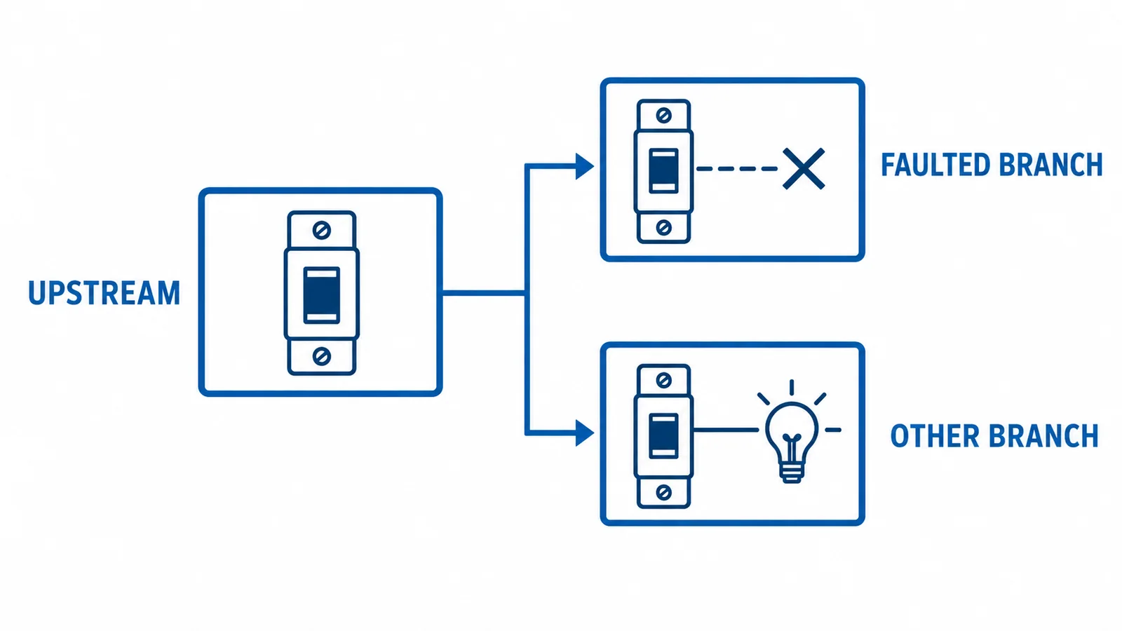
The assembly is a separate boundary: IEC 61439-2:2020 addresses low-voltage power switchgear and controlgear assemblies. A suitable standalone breaker does not by itself establish the assembly’s short-circuit or temperature-rise suitability.
Check coordination by current region
At overload currents, compare long-time pickup and delay bands, including tolerances. At intermediate short-circuit currents, examine short-time functions and any intentional delay. At high fault currents, instantaneous trips, current-limiting behavior and internal overrides can dominate; curves that look separated at lower currents may converge. Ground-fault selectivity is another study where those functions are present. Use the exact combination of device frames, trip units, settings and supply voltage, not a generic family chart.
The useful acceptance statement is therefore specific: “selective up to the stated prospective current under these settings and operating conditions,” or “full selectivity over the installation’s prospective range” only if supported by applicable test/coordination data. Where a manufacturer offers tested pair tables, obtain the evidence as project documentation; OHELE does not endorse a vendor or treat a marketing chart as an industry rule.
Do not trade delay for continuity without a safety review
An upstream short-time delay may improve fault selectivity, but it extends fault duration at some locations. Check equipment short-time withstand and have the arc-flash study reassessed when clearing time changes. Zone-selective interlocking or another engineered scheme may offer a different tradeoff, but it needs compatible devices, a verified design and commissioning evidence. Neither a faster trip nor a selective trip can be assumed from the technology name alone.
Procurement and verification checklist
- Define the required continuity zone and the worst credible source configurations.
- Verify each breaker’s voltage, continuous-current and interrupting ratings against the actual installation.
- Compare min/max fault currents with the exact pair’s time-current and coordination data, including tolerances and override behavior.
- Check conductor protection, assembly short-time withstand and the effect of intentional delays on incident-energy results.
- Record selected settings and recheck coordination after device replacement, source changes or setting changes.
This is a selection framework, not field setting instructions. Isolation, testing and commissioning belong to qualified personnel under the site’s procedures.