
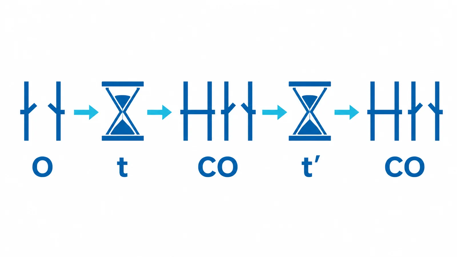
An operating sequence describes a breaker’s assigned ability to perform specified open and close–open operations at stated intervals; it is not an instruction to reclose every faulted feeder. In the IEC notation O–t–CO–t′–CO, O is an opening operation, CO is a close–open cycle, and t and t′ are defined intervals. The exact intervals must come from the applicable rating declaration and edition, not from the letters alone.
This article concerns three-phase AC circuit breakers above 1 kV within the scope of IEC 62271-100:2021+A1:2024. Verify the adopted edition in a project specification. IEEE/ANSI projects use their own ratings framework and should not assume direct equivalence from a similar-looking sequence.
Read the timeline, not just the shorthand
| Element | Meaning | Specification question |
|---|---|---|
| O | Breaker opens | What fault/interruption duty applies at the first operation? |
| t | Interval before the next close–open cycle | Is rapid automatic reclosing required? |
| CO | Closes, reaches its defined closed state and opens again | Can the mechanism and control supply support a close onto a persistent fault? |
| t′ | Interval before another close–open cycle | What recovery and recharge conditions apply? |
| CO | Further close–open cycle | Is this included in the assigned and tested duty? |
The notation is not merely a mechanical cycling count. Under the applicable test program, operations can relate to making and breaking duties and the mechanism’s ability to execute the assigned sequence. However, a sequence marking alone does not tell you the available short-circuit current, transient recovery voltage, special switching duty or the status of auxiliary energy storage. These are separate checks in the broader MV circuit-breaker ratings crosswalk.
Rapid reclosing is an application decision
An overhead line may have a reclosing philosophy that differs from a cable feeder, transformer or motor circuit. Whether automatic reclosing is allowed—and with what dead time, supervision and lockout logic—depends on system protection design, equipment, operating policy and the hazards of re-energizing the connected load. Do not infer permission to reclose from a breaker nameplate. Reclosing onto a persistent fault is a capability that must be assessed, not an operating objective.
For a procurement schedule, request the exact sequence as declared for the offered breaker, the governing standard and edition, the applicable short-circuit making/breaking evidence, control-voltage range and stored-energy/recharge requirements. Check that the relay and control scheme impose the intended inhibit and lockout conditions. A site may intentionally use a breaker capable of a fast sequence while disabling auto-reclose in service.
A practical acceptance check
Write the required duty in plain language first: “open on a fault, then [reclose permitted or prohibited], then [maximum number of attempts] under [specified control and network conditions].” Map that to the declared breaker sequence and verify the protection/control logic separately. If the specification contains only O–CO shorthand without intervals or an edition, it is incomplete. Ask the supplier for the complete assigned rating and supporting test documentation; a qualified engineer must approve the system application.