
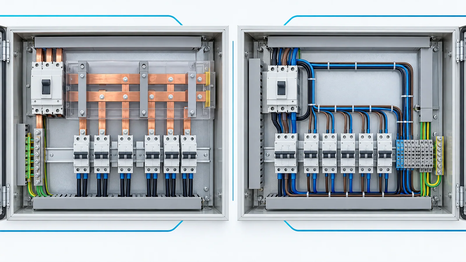
An engineered busbar system is often attractive when a low-voltage panel distributes substantial current to repeated devices in a compact, stable layout. Discrete cable and terminal blocks usually fit smaller or more variable branches and can be easier to change. Neither architecture is intrinsically safer or cheaper. Both require a verified current path, fault-duty check, temperature-rise review, insulation and spacing, protective-device coordination, and assembly documentation.
This comparison concerns distribution inside industrial panels. It is distinct from busway versus bare busbar distribution between equipment, and it does not replace the detailed sizing of a particular bar or cable.
Compare the same electrical job
Define the source, downstream devices, operating current, prospective short-circuit current, enclosure, ambient conditions, access, and expected modifications before drawing either layout. A comparison between a tested busbar assembly and a loosely specified wire harness is not a fair design comparison.
| Decision dimension | Engineered panel busbar | Cable and terminal blocks | What must be checked |
|---|---|---|---|
| Repeated high-current paths | Compact, consistent geometry may help | Multiple conductors and terminations can accumulate | Current rating and temperature rise of entire path |
| Small or mixed branches | May need adapters or branch modules | Flexible routing and circuit-by-circuit changes | Terminal, wire and protective-device ratings |
| Fault forces and heating | Bar supports and joints carry mechanical duty | Cable restraint and terminals carry duty | Prospective fault and verified short-circuit withstand |
| Space | Can reduce wiring volume in regular layouts | Can fit irregular device positions but needs bend space | Real enclosure geometry and accessibility |
| Modifications | Extensions may depend on system components | Re-routing may be easier if spare space exists | Documentation, safe isolation and re-verification |
| Maintenance | Fewer distinct connections in some topologies | More identifiable individual conductors in some topologies | Joint access, inspection and replacement method |
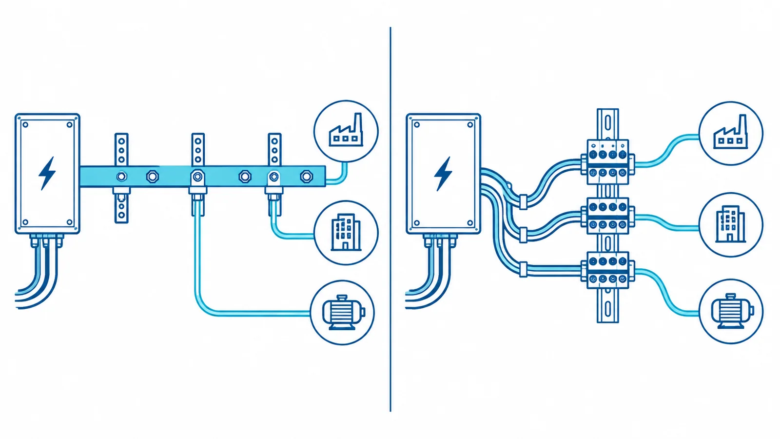
The table is a screening framework, not a rating chart. The actual components and assembly design determine which option is viable.
Follow one branch from source to load
Consider a conceptual panel with one incoming feeder supplying several protected outgoing circuits. In the busbar version, current passes through the incoming connection, main bar and supports, a take-off interface, the branch protective device, and the outgoing connection. In the cable version, it passes through an incoming terminal or distribution device, individual cable runs, possibly intermediate terminal blocks, branch protection, and the outgoing connection.
Every joint in either chain needs an approved mating interface, conductor or bar rating, mounting and torque or clamping method, and access for inspection. The limiting component or condition governs the usable path. It is incorrect to size only the main bar by its cross-section, or only the cable by a table ampacity, and then assume the entire panel is covered.
The copper-busbar ampacity and derating guide addresses bar thermal inputs; cable sizing for breaker feeders addresses the cable side. The full assembly still needs its own verification.
Fault duty can reverse the initial preference
At a high prospective fault level, the busbar supports, joints and insulating components must withstand electromagnetic and thermal effects until protection clears. Cable systems also require suitable short-circuit withstand, restraint and terminations. A bar may look mechanically stronger but can fail at its supports; a flexible cable may be easier to route but can impose forces on a weak terminal. Neither visual impression is evidence.
Obtain the available short-circuit current at the panel, the protective-device clearing behavior and the assembly’s verified short-circuit rating or permitted design method. Do not substitute the interrupting rating of one breaker for the rating of the complete assembly. IEC 61439-1:2020 establishes general construction and verification requirements for low-voltage switchgear and controlgear assemblies, to be applied with the relevant product part. In U.S. industrial control panels, the UL 508A SCCR framework is a separate route and uses the actual panel components and arrangement.
Temperature and insulation are system properties
Heat depends on current, conductor resistance, joints, grouping, enclosure ventilation, ambient conditions and duty cycle. Short, broad busbars can make a compact route, but close spacing and enclosure heat still matter. Cables may move heat along a different route, yet bundles, ducts and bend constraints can increase temperature. Do not infer temperature-rise compliance from an isolated component rating.
The physical layout must also maintain the required electrical separation after branch taps, covers, wire lugs and service access are considered. Busbar insulation, barriers, shrouds and supports are part of the assembly. Cable insulation and terminal-block barriers do not remove the need to check clearance, creepage, touch protection and mechanical support.
The compact-switchgear busbar sizing guide explores the dense-layout case. Do not copy its dimensions into a different enclosure without recalculation and verification.
When each architecture tends to fit
Choose an engineered busbar architecture when the layout is repetitive, current paths are substantial, space is tight, approved taps are available, and the exact system has credible thermal and short-circuit evidence. Its higher up-front engineering or proprietary-system cost may be justified by repeatability across many panels, but this must be measured for the actual build volume.
Choose cable and terminal blocks when branch positions vary, conductor sizes are mixed, modification is expected, and the available enclosure can accommodate safe bend radius, segregation and inspection. Its flexibility is valuable only if conductor preparation, terminal selection and routing stay controlled. A crowded harness is not automatically a low-cost design.
A hybrid is common in concept: a verified main distribution bar or power distribution block, then cable to protected branches. Treat the transition itself as a rated connection with documented fault and thermal performance.
A five-gate design review
- Duty: Record voltage, continuous and peak operating current, load diversity, prospective fault, clearing time and environment.
- Architecture: Draw each current path and all connection interfaces. Count required branch points, not just the main path.
- Component evidence: Obtain ratings, accepted conductors or taps, supports, accessories, and installation instructions for the exact selected system.
- Assembly verification: Check temperature rise, short-circuit withstand or SCCR, insulation, touch protection, protective-device coordination, and documentation under the applicable jurisdiction and standard.
- Life-cycle review: Compare assembly labor, space, inspection access, likely changes and replacement availability for the same acceptable design.
For any physical inspection or alteration, qualified personnel must follow the site procedure. In U.S. general-industry work on exposed fixed equipment, OSHA 1910.333 governs de-energization and verification; this architectural guide is not an energized-work instruction.
The best choice is the one whose complete current path, assembly behavior and maintenance method are documented for the actual panel—not the one with fewer visible wires.