
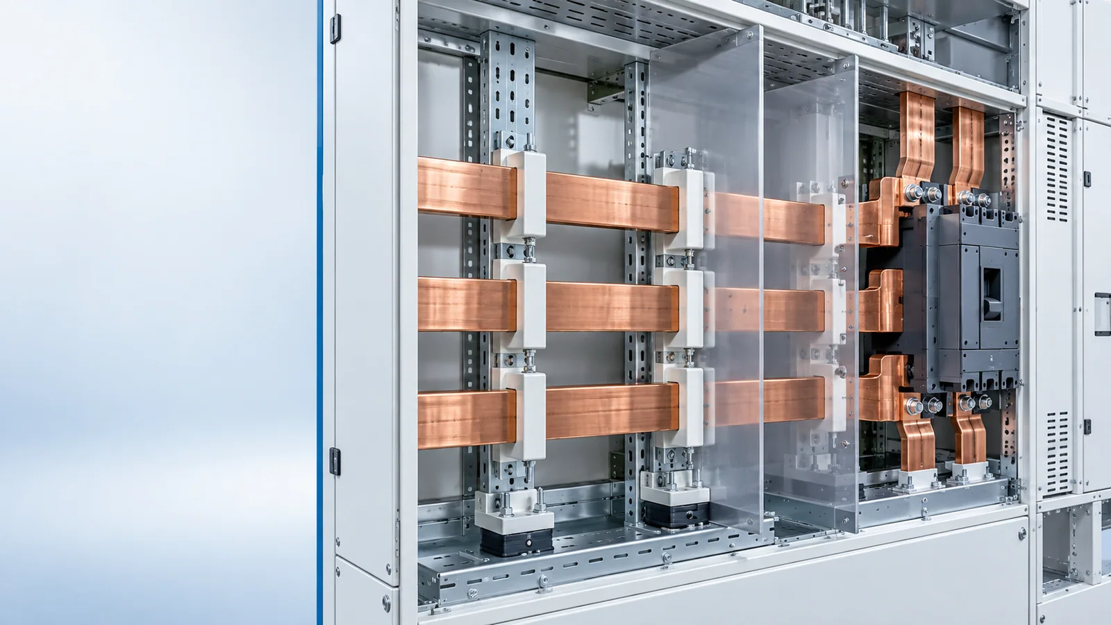
To size a busbar for compact low-voltage switchgear, choose a preliminary copper area from the continuous current, calculate hot conductor and connection losses, place those losses in the actual enclosure heat balance, and iterate geometry until every bar, joint and device terminal remains within its permitted temperature. Then check short-circuit withstand and verify the assembly by a route allowed by the applicable IEC 61439 product standard.
A current-density shortcut can produce a starting area. It cannot prove a compact panel design because reducing enclosure volume changes cooling, component interaction and local air temperature.
Scope and required result
This workflow covers rigid copper main busbars in enclosed low-voltage switchgear and controlgear assemblies. It is intended for preliminary engineering and design documentation. It does not replace the assembly manufacturer’s design rules, type-test evidence, product-specific IEC 61439 part, or qualified review.
The required result is not simply “800 mm² copper.” It is a calculation and verification file containing:
- current and service conditions;
- selected geometry and conductor material;
- hot resistance and loss for each current path;
- device, joint and auxiliary losses;
- enclosure geometry and cooling assumptions;
- predicted or measured temperatures;
- short-circuit duty and support arrangement;
- manufacturing controls and the selected verification route.
For baseline conductor physics and the limits of generic charts, first see Copper Busbar Ampacity: AC, DC, and Derating.
Step 1: freeze the design inputs
Do not select a section until these inputs are controlled.
Electrical duty
- assembly rated current and circuit group loading;
- continuous load profile and rated diversity factor;
- AC or DC, frequency and harmonic spectrum;
- neutral current, including triplen harmonics where relevant;
- emergency or overload duty and permitted duration;
- maximum and minimum prospective short-circuit current;
- protective-device clearing time and peak current.
Service conditions
- maximum ambient air temperature at the installation;
- altitude and cooling-medium assumptions;
- indoor/outdoor location, solar gain and nearby heat sources;
- pollution, humidity and condensation controls;
- wall recess, adjacent assemblies and obstruction of cooling surfaces.
Mechanical and enclosure constraints
- usable compartment dimensions;
- bar orientation, bend radii and phase spacing;
- number and location of supports;
- partitions and segregation;
- cable and device terminal positions;
- ventilation openings or forced-air system;
- required clearances, creepage distances and access.
Use maximum credible coincident loading, not the arithmetic sum of nameplate currents when the design basis legitimately uses diversity. Record the diversity assumption so it can be reviewed and verified.
Step 2: select a preliminary geometry
A simple current-density expression is:
Apre = I / Jpre
where:
- Apre is preliminary copper area in mm²;
- I is design current in A;
- Jpre is a provisional current density in A/mm².
The equation is geometry selection, not thermal verification. Do not copy a generic Jpre from an unrelated cabinet and present the result as compliant. Derive it from a verified reference design, project rule or conservative internal design basis whose enclosure and service conditions are known.
Once an area is selected, choose width, thickness and number of bars. Equal area does not mean equal thermal behavior. A wider, thinner bar generally exposes more surface area than a thick compact bar, while phase spacing and orientation change convection and AC proximity effects.
Step 3: calculate the hot loss budget
For each straight segment:
R20 = ρ20L / A
Rθ = R20[1 + α20(θ − 20)]
Pbar = I²Rac,θ
Use effective AC resistance at operating temperature where applicable. The AC/DC resistance ratio must match the actual bar geometry, phase arrangement and frequency.
Build the loss budget by compartment:
| Heat source | Calculation input | Location |
|---|---|---|
| Main bars | hot AC resistance and RMS current | busbar chamber |
| Joints and links | validated resistance or measured loss | each interface |
| Circuit breaker | declared loss at the applied current/settings | device compartment |
| Cable terminations | conductor and connection loss | cable chamber |
| Control transformer/power supply | operating loss | auxiliary section |
| Contactors/relays | coil and pole loss under duty | functional unit |
| External heat | solar or adjacent source | affected surfaces |
Do not use component marketing heat-loss figures without checking the exact frame, current, pole arrangement, terminals and operating condition. Product-specific data belongs in the engineering record even when it is not an OHELE publication source.
Worked preliminary example
Assume a three-phase, 50 Hz assembly with:
- design current: 1,600 A;
- one 1 m main-bar segment per phase;
- candidate copper bar: 100 mm × 10 mm per phase;
- candidate area: 1,000 mm²;
- illustrative copper resistivity at 20°C: 0.01724 Ω·mm²/m;
- estimated conductor temperature for loss iteration: 85°C;
- illustrative temperature coefficient: 0.00394/°C.
Cold resistance:
R20 = 0.01724 / 1,000 = 17.24 µΩ per phase-metre
Temperature correction:
R85 ≈ 17.24 × [1 + 0.00394 × 65] = 21.65 µΩ
DC-equivalent straight-bar loss:
Pphase ≈ 1,600² × 21.65 µΩ = 55.4 W/m
P3φ ≈ 166 W/m
If a validated analysis gives an AC resistance factor of kac for the exact geometry, use:
P3φ,AC = 166 × kac
Do not invent kac. If it is unknown, the open item must remain visible and be resolved by an accepted calculation, simulation, comparison or test. Add joint and device losses separately; they are not included in the 166 W/m result.
Step 4: model the enclosure, not just the bars
Compactness reduces external cooling surface and can place several heat sources in the same rising air path. Internal temperature is therefore position-dependent: inlet air, lower chamber, upper chamber and device terminals may differ.
IEC TR 60890:2022 specifies a calculation method for air temperature rise inside enclosures for low-voltage switchgear and controlgear assemblies. Its published scope highlights enclosure material, uneven power distribution, natural and forced ventilation management, adjacent walls, solar radiation and power-loss calculation. It is primarily aimed at enclosed or partitioned assemblies and states defined validity conditions.
For a calculation route:
- divide the assembly into the thermal sections required by the method;
- assign losses to their actual vertical and horizontal locations;
- calculate effective cooling surfaces, accounting for walls and adjacent structures;
- define ventilation openings and whether airflow is natural or forced;
- calculate internal air rise;
- add the project ambient;
- compare the predicted air and component temperatures with applicable limits.
If the design lies outside the method’s validity—for example because airflow, geometry or loading is not represented—use an accepted alternative such as testing or a validated design comparison.
Step 5: iterate geometry intelligently
If the first model is too hot, changing bar area is only one lever.
| Design lever | Likely benefit | Boundary to check |
|---|---|---|
| Increase bar area | reduces resistance and conductor loss | space, cost, bends, terminals |
| Use wider/thinner bars | increases exposed surface; may reduce some AC effects | mechanical stiffness and support |
| Increase phase spacing | can reduce proximity heating | enclosure width and insulation coordination |
| Reposition heat sources | prevents cumulative hot-air path | wiring, access and segregation |
| Improve natural ventilation | lowers internal air rise | IP rating, contamination and fire barriers |
| Add forced ventilation | increases heat removal | fan reliability, filters, alarms and loss of airflow |
| Reduce joint resistance | removes local hotspots | repeatable manufacturing process |
| Split into parallel paths | can add surface area | current sharing, symmetry and connection balance |
Recalculate the complete loss and heat balance after each material change. A wider bar may improve cooling but require a different phase arrangement; a fan may lower air temperature but create a single point of failure.
Step 6: check interfaces and hotspots
The hottest point may be a breaker terminal, splice or transition link rather than the main bar.
For every interface, record:
- conductor materials and plating;
- overlap and contact geometry;
- fastener and washer system;
- assembly torque or tension method;
- validated joint resistance or loss;
- expected thermal expansion and mechanical load;
- accessible surface and adjacent insulation;
- inspection or process-control requirement.
Infrared scanning during a controlled load test can locate temperature patterns, but emissivity, viewing angle, reflected energy and inaccessible interfaces can mislead. Use appropriate instruments and competent personnel; thermography does not replace direct verification required by the applicable standard.
Step 7: verify short-circuit withstand
The continuous-current design must also withstand:
- thermal energy during the protective-device clearing interval;
- peak electromagnetic forces between phases and parallel bars;
- forces at bends, offsets and terminals;
- mechanical loads on supports and enclosure structure;
- the specified sequence and condition after the event.
Area alone is insufficient. Bar spacing, support span, support material, fasteners and peak current determine mechanical stress. The applicable IEC 61439 verification provisions and tested-reference rules govern the acceptable evidence.
Step 8: choose the assembly verification route
IEC 61439-1:2020 provides the general rules for low-voltage assemblies and states that conformity uses the relevant product-specific part together with Part 1. For assemblies not covered by Parts 3 onward, the official scope says Part 2 applies.
The project team should identify:
- relevant IEC 61439 product part;
- design-verification route for temperature rise;
- design-verification route for short-circuit withstand;
- routine verification for each manufactured assembly;
- reference design and allowed deviations, if comparison is used;
- test arrangement, instruments and loading, if test is used;
- calculation method and validity checks, if calculation is used.
“Designed to IEC 61439” is not an evidence package. The file must show how the specific design was verified.
Compact-switchgear calculation sheet
Use one line per heat source and one section per enclosure zone.
| Field | Required entry |
|---|---|
| Assembly and circuit | identifier, rated current, diversity/group loading |
| Service | ambient, altitude, installation, wall/adjacent conditions |
| Conductor | material, width, thickness, quantity, length, orientation |
| Electrical | RMS current, frequency, harmonics, hot resistance, AC factor |
| Connections | count, resistance/loss basis, terminal arrangement |
| Devices | model-specific power loss at the design duty |
| Enclosure | dimensions, material, partitions, cooling surfaces, openings |
| Results | air rise by zone, predicted conductor/terminal temperatures |
| Fault duty | RMS, peak, duration, support geometry |
| Verification | standard part/edition, route, evidence reference, limitations |
Stop conditions
Do not release the section when:
- local ambient or fault duty is unknown;
- a current-density rule is the only thermal evidence;
- component losses are absent from the enclosure model;
- an AC factor is assumed without geometry-specific support;
- parallel paths have no current-sharing assessment;
- the design exceeds the calculation method’s applicability;
- the short-circuit support system has not been verified;
- the completed assembly has no documented IEC 61439 verification route.
Bottom line
Compact switchgear busbar sizing is a coupled electrical, thermal and mechanical problem. Select an initial area, calculate hot losses, distribute every heat source in the actual enclosure, iterate geometry and ventilation, then verify short-circuit withstand and the assembly. The final deliverable is traceable evidence for the complete arrangement—not a cross-section obtained from a generic A/mm² value.