
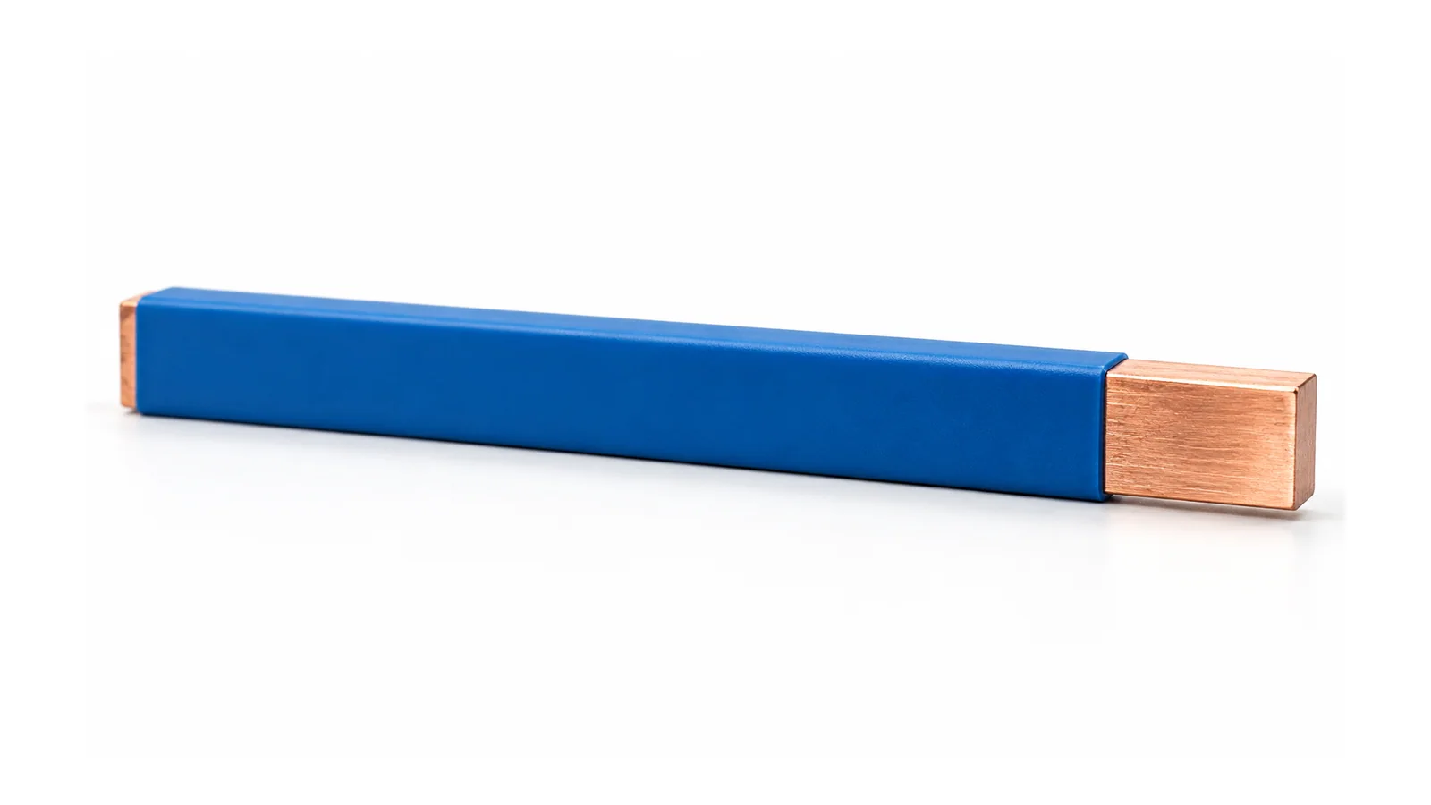
Choose busbar insulation by the surfaces it must cover, the connections that must remain usable, and the evidence for the finished assembly. Heat-shrink sleeves, epoxy coatings and molded insulation can each serve a suitable design, but their names do not establish a voltage rating, temperature limit or permission to reduce spacing.
There is also a terminology trap: heat-shrink and molding describe application methods; epoxy describes a material family. A molded system may itself use an epoxy compound. Compare actual constructions, not three supposedly exclusive materials.
This comparison concerns rigid copper conductors inside guarded industrial low-voltage (LV) assemblies. It does not specify medium-voltage encapsulation, an insulation thickness or a field coating procedure. The goal is a defensible comparison of insulation systems for the same conductor route.
What each construction means
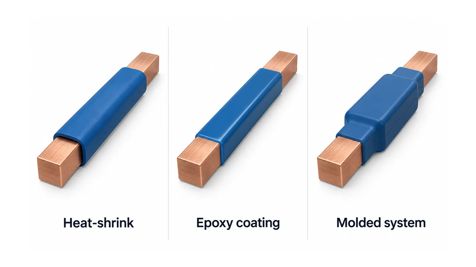
A heat-shrink sleeve is a preformed insulating covering fitted over the conductor and recovered by the specified heating process. Its fit and transitions are part of the construction, not merely its nominal starting size.
An epoxy-coated busbar has a cured resin covering over designated surfaces. Powder application and subsequent curing are one manufacturing route; “epoxy” alone does not identify the process, formulation or coverage.
In a molded system, insulation is formed to a defined shape around a conductor, or a separately molded insulating part is assembled around it. Specify which arrangement is intended: encapsulation and a removable cover are not equivalent boundaries.
The institutional Copper for Busbars coatings annex describes powder coating and heat-shrink sleeves, and highlights coating continuity and edge geometry. This 2014 guide is useful for physical principles; its example material temperatures and older standards references are not universal limits for today’s products.
Compare the same bar, interfaces and duty
Hold conductor geometry, connection positions, electrical duty and enclosure conditions constant. Otherwise, a claimed insulation advantage may actually come from changing the copper route or the panel.
| Review dimension | Heat-shrink sleeve | Epoxy surface coating | Molded insulation system |
|---|---|---|---|
| Coverage definition | Identify sleeve length, recovered fit and end transitions | Identify coated faces, masked areas and coating termination | Identify encapsulated regions or assembled cover parts and their interfaces |
| Shape dependency | Check the actual bar profile, bends and fit restrictions | Check how edges, holes and recesses are treated | Check whether the tooling or part geometry matches the exact bar revision |
| Joint access | Define uncovered mating areas and any separate joint protection | Define masked contact areas and treatment around fasteners | Define how the joint is reached without damaging or defeating the insulation |
| Production evidence | Document accepted material and recovery process | Document material, preparation, application and cure controls | Document material, forming/assembly process and interface controls |
| Changes and servicing | Assess sleeve damage and the approved replacement method | Assess coating damage and the approved disposition | Assess conductor/part replacement and whether the system can be disassembled |
| Thermal and electrical acceptance | Verify the installed configuration | Verify the installed configuration | Verify the installed configuration |
The matrix is an engineering review aid, not a ranking or a claim that one process always has fewer defects. A well-controlled construction in any column is more informative than its generic label.
Define the insulation’s job before comparing cost
State what the covering is intended to provide: a specified solid-insulation boundary, separation within the assembly, protection against incidental mechanical contact, or another documented function. Do not assume that a colored covering is a complete shock-protection system.
Draw where the insulation starts and stops. Include mounting points, holes, bar ends, joints and transitions to other insulating parts. Ask what maintains the electrical boundary at each location, and which areas remain exposed conductive metal.
IEC 60664-1:2020+AMD1:2025 addresses clearance, creepage and solid-insulation criteria within its LV scope. Its public description does not establish a blanket spacing reduction for coated busbars. The applicable equipment requirements, electrical stresses and environment must determine the actual solution.
Likewise, ordinary paint and an evaluated electrical insulation system are not interchangeable. A surface appearing covered is not evidence that the intended insulation performance has been demonstrated.
Ask for material evidence and process evidence separately
An insulation material can have relevant properties without the finished part having the same demonstrated performance. Conversely, a repeatable process does not compensate for an unsuitable material.
For each candidate, request the identified formulation or grade, relevant electrical and thermal characteristics, exposure compatibility, manufacturing controls and the evidence applying to the finished construction. Record which characteristics are material-level and which were evaluated in the actual arrangement.
Scope differences matter even within resin standards. IEC 60455-1:1998 addresses resin-based reactive compounds for electrical insulation and explicitly excludes reactive compounds used as coating powders. Citing that document beside every epoxy construction would therefore obscure, rather than settle, the material evidence question.
This is not a request to reproduce a supplier’s proprietary recipe. It is a request for enough controlled information to identify the construction and justify its intended use. If the formulation, thickness, coverage or process changes, establish which evidence remains applicable before approving the revision.
Keep heat and supports outside the marketing comparison
An insulating layer changes the conductor’s heat-transfer boundary. That observation alone does not establish whether a particular covered bar will run hotter or cooler: surface characteristics, geometry, airflow, joint losses and neighboring equipment also matter.
Use the same loading and enclosure assumptions for all candidates. Identify the evidence for the conductor, the insulated length and the connection region. An isolated material temperature rating is not a temperature-rise result for the complete current path. The separate copper-busbar ampacity guide addresses capacity and derating inputs.
Insulation also does not establish mechanical restraint or short-circuit withstand. Show the bar supports and connection interfaces independently of the covering. IEC 61439-1:2020 supplies general construction and verification requirements for LV assemblies, used with the applicable product part. Component or material evidence does not replace assembly verification.
A change-review example: adding a branch connection
Consider a hypothetical rigid copper route with a proposed new branch connection. No dimensions, ratings, test results or cost savings are assumed.
For a sleeve construction, ask whether the new connection falls within a covered region and how an approved electrical boundary would be restored around the joint. For a coated construction, ask how the required contact area would be defined and whether the revised manufacturing sequence preserves the accepted construction. For a molded system, ask whether the existing part provides the new interface or whether a new part/tooling revision is needed.
For all three, hold release until the connection design, insulation boundary, thermal basis, supports and service method are resolved. Cutting a covering, drilling a coated bar or modifying a molded part is not a neutral change merely because the copper still fits.
This example suggests a conditional choice: sleeves may suit a documented covering operation on compatible geometry; a controlled coating may suit repeatable surface coverage; a shaped molded system may suit a defined three-dimensional interface. None of these conditions establishes performance without its evidence.
What to retain before releasing the design
Keep an equal-duty comparison drawing, material identification, manufacturing/assembly revision, insulation-boundary drawing, thermal and fault-duty evidence, inspection criteria and approved damage/repair disposition. Record unresolved items and their approval owner.
If the underlying choice is between a flexible insulated link and a fixed bare rail, use the separate flexible-insulated-versus-bare layout comparison. If the distribution architecture itself is unresolved, start with panel busbar versus block-and-cable wiring.
The successful comparison ends with an accepted construction for a named application—not a universal winner among heat-shrink, epoxy and molded insulation.
Sources
- Copper for Busbars — Guidance for Design and Installation, revised May 2014, coatings annex: physical/process background, not current universal ratings.
- IEC 60455-1:1998: resin-compound scope and powder-coating exclusion.
- IEC 60664-1:2020+AMD1:2025: insulation-coordination public scope.
- IEC 61439-1:2020: LV assembly general rules and verification scope.