
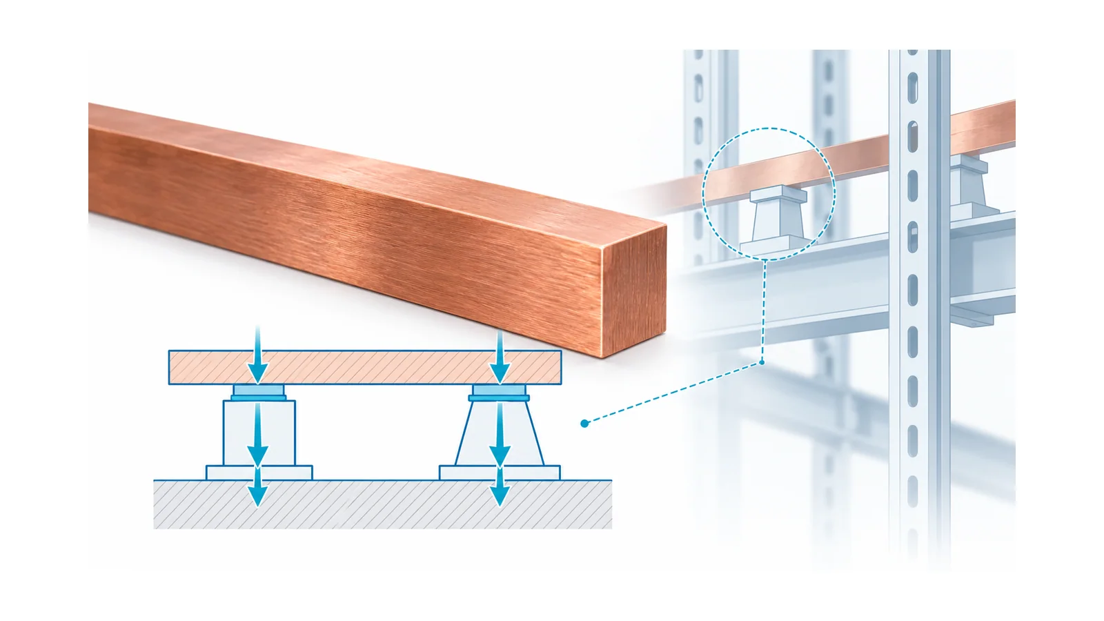
Busbar short-circuit mechanical verification starts with the fault-current waveform and ends with a demonstrated load path through conductors, joints, supports and their mounting structure. Operating ampacity does not establish that result. Peak electromagnetic loading can challenge a support or reduce an insulation gap even when the conductor’s separate thermal check is satisfactory.
The key questions are what current flows through each segment, what force that geometry produces, and what movement and reactions the complete structure can tolerate. A single calculated force is not a busbar withstand rating.
This article explains that mechanical subtask for power-conversion and energy-storage installations. It includes an elementary sensitivity calculation, not a certified busbar design, a support-span table or a chemistry-independent battery fault model.
Separate the mechanical study from current sizing
The existing stationary ESS busbar-sizing guide owns the operating-current, loss and cabinet-temperature workflow. The EV battery busbar guide adds vehicle duty and pack validation. Here, energy storage system (ESS) sizing and electric-vehicle (EV) pack design remain separate tasks; the focus is fault-induced mechanical loading.
Three quantities answer different questions:
| Quantity | Mechanical or thermal question |
|---|---|
| Instantaneous currents and their directions | What electromagnetic loading acts at this moment? |
| Current squared integrated over clearing time | What thermal exposure must the applicable conductor/joint model assess? |
| Force history, stiffness and mass | What dynamic displacement, conductor stress and support reaction occur? |
For a simple arrangement, force grows with the product of the interacting currents. Heating also involves current squared, but a similar mathematical dependence does not make the two acceptance checks equivalent. The current peak and the exposure duration must both be retained.
Establish the fault states before modeling copper
Define credible fault locations, connected sources, operating configurations and protective-device behavior. Identify which rail segments and branches actually carry each source contribution. The total current at a fault is not necessarily the current through every conductor segment.
For a battery energy storage system (BESS), include the relevant parallel battery paths and power-conversion/DC-link contributions on a justified system basis. State battery condition, source impedance and the validated clearing behavior. A normal battery management system current limit is not automatically a fault-interruption mechanism for a shorted copper path.
For alternating-current (AC) faults, preserve the asymmetry and time-dependent behavior needed by the accepted mechanical method. Do not substitute an arbitrary multiple of a symmetrical root-mean-square (RMS) current for the verified peak basis. For direct-current (DC) faults, establish the applicable current rise, peak, decay and interruption sequence rather than borrowing an AC factor.
If the design credits current limitation, obtain evidence for the exact protective device, fault condition and circuit. Its nominal current rating alone cannot establish peak let-through current or clearing exposure.
Choose the calculation method within its scope
The International Electrotechnical Commission (IEC) public scope for IEC 60865-1:2011 covers mechanical and thermal short-circuit effects, including electromagnetic effects on rigid and flexible conductors. It explicitly deals with AC systems. Its reference to other documents does not turn it into a general DC busbar design standard.
IEC 61660-2:1997 addresses mechanical and thermal effects on rigid conductors in DC auxiliary installations of power plants and substations described by Part 1. That is a defined auxiliary-system scope, not automatic coverage of every lithium-ion battery cabinet or converter-fed DC network.
| Installation boundary | Method question to resolve |
|---|---|
| AC busbar arrangement | Are the geometry, fault-current basis and structural assumptions covered by the selected AC method? |
| Stationary auxiliary DC arrangement | Does the installation and source model fit the selected auxiliary-DC method? |
| BESS or converter DC path | What validated source, protection and structural models apply to the actual system? |
Use the full applicable method and engineering review for the project. Catalog descriptions establish boundaries; they do not supply all geometry factors, dynamic factors or acceptance criteria.
Use the parallel-current equation to understand sensitivity
For two very long, thin, straight parallel conductors in a nonmagnetic surrounding medium approximated as free space, the elementary force magnitude per unit length is:
f = μ₀ × |I₁I₂| / (2πd)
Here f is N/m, I₁ and I₂ are instantaneous currents in A, d is separation between the idealized current filaments in m, and μ₀ ≈ 4π × 10⁻⁷ N/A². Same-direction currents attract; opposite-direction currents repel. Rice University’s OpenStax discussion derives this relationship.
This is a teaching model. Real flat busbars have finite width and thickness, multiple interacting paths, bends, nearby magnetic material and nonuniform current distribution. Their force distribution can require a different calculation or field model.
Assume equal opposite-direction instantaneous currents and three hypothetical cases:
| Case | Current magnitude in each filament | Separation | Elementary force magnitude per length |
|---|---|---|---|
| A | 20 kA | 80 mm | 1,000 N/m |
| B | 30 kA | 80 mm | 2,250 N/m |
| C | 20 kA | 40 mm | 2,000 N/m |
For Case A:
f = (2 × 10⁻⁷) × 20,000² / 0.080 = 1,000 N/m
Increasing current by 50% raises the calculated loading by 2.25 times. Halving separation doubles it under this model. The values are not measured busbar loads or permissible support ratings.
Dimensional check: (N/A²) × A² / m = N/m. The denominator is the defined filament separation, not an arbitrary edge clearance copied from an insulation drawing.
Carry the load through the structure
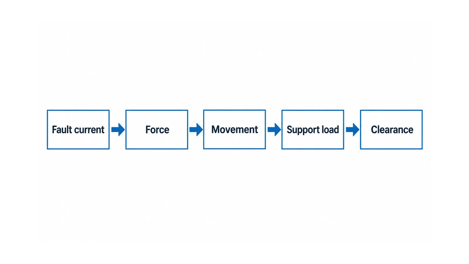
Determine how the force acts on each span and how the resulting loads reach supports, fasteners, joints and the mounting structure. Support spacing changes the structural response even if the electrical force per metre is unchanged. Conductor orientation and section shape determine bending stiffness and the direction in which movement is most significant.
Check the assumed restraint at each support. A simply supported span, a clamped span and a continuous multi-span assembly do not have identical moments, reactions or deflections. Real joints and supports may not behave like ideal restraints, particularly after temperature exposure, assembly tolerances or aging are considered.
Static peak loading is not automatically conservative for every structure. The fault duration and force variation can interact with mass, damping and natural frequencies. Use the dynamic treatment required by the accepted method; do not introduce an unverified amplification factor to make the calculation appear complete.
A structural analysis should identify at least:
- governing conductor stress and movement in the relevant direction;
- support reactions and local stresses, including loads transferred into the mounting structure;
- joint and fastener loads for the actual assembly;
- displacement relative to adjacent live parts, grounded metal and insulation interfaces;
- any permanent change that conflicts with the required post-fault condition.
Preserve insulation and validate the assumed restraints
Mechanical survival and insulation performance are linked. An intact conductor that moves toward another potential can still defeat the required electrical separation. Evaluate the worst relevant displaced configuration, assembly tolerances and the condition after the specified fault duty.
Material strength alone cannot establish support suitability. The selected support arrangement, fastening, mounting surface, environmental condition and production tolerances must match the analysis or test evidence. Do not interpret a generic insulator datasheet load as the rating of the complete mounted assembly.
For grid-integrated electrochemical storage, IEC 62933-5-2:2025 places safety within the system and subsystem interactions over the life cycle. Its public scope is not a busbar-force equation or a substitute for mechanical verification of the actual DC path.
Keep a mechanical acceptance record
Retain fault cases, per-segment current waveforms, protective-device assumptions, conductor/support geometry, restraint and material basis, calculation method, force distribution, stress/displacement results and acceptance criteria. Link those records to the exact assembly configuration and any test evidence credited.
A change to support spacing, a branch connection, a joint, rail separation or a current-limiting device can invalidate the earlier result. Route it through the mechanical and protection reviews, even when the operating ampacity remains unchanged.
Fault testing involves hazardous energy and belongs in qualified, controlled facilities under approved procedures. Never improvise a short-circuit test on an installed battery cabinet. The design is ready when the complete mechanical load path and insulation consequences are supported, not when the simplified equation produces a small number.