
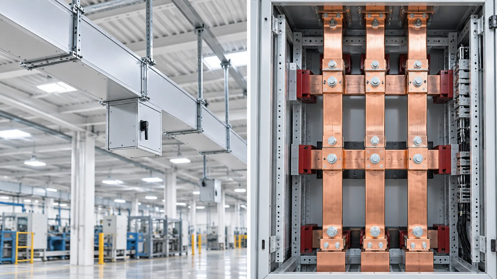
Busway—or busbar trunking—is a complete enclosed distribution assembly with conductors, enclosure, joints, supports and often tap-off provisions. A busbar is the conductor itself or a conductor system integrated into equipment. Choose busway when the project needs a modular, verified route between equipment or repeated tap-offs. Choose equipment-integrated busbars when the conductor remains within a switchboard, panel, battery system or custom assembly whose designer controls cooling, supports and interfaces.
The comparison is not “metal box versus copper.” It is a complete-system procurement decision versus a conductor-level design decision.
Definitions and scope
IEC 61439-6:2012 covers low-voltage busbar trunking systems (busways) up to 1,000 V AC or 1,500 V DC within its scope and specifies service, construction, technical and verification requirements. It is read with IEC 61439-1.
Equipment busbars normally form part of another assembly. Their thermal, dielectric and short-circuit performance is verified through the applicable product or assembly standard. A bare bar’s material and dimensions do not constitute an assembly rating.
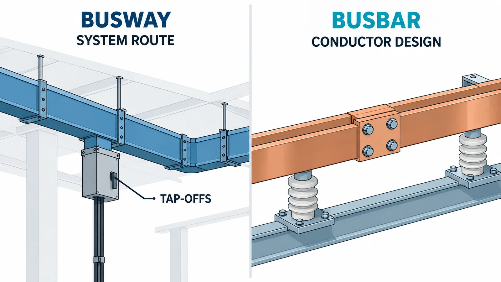
Decision table
| Decision dimension | Busway / busbar trunking | Equipment-integrated busbar |
|---|---|---|
| Product boundary | complete enclosed distribution system | conductor inside another assembly |
| Typical route | between transformers, switchboards, floors or process areas | within switchgear, panels, converters, batteries or machines |
| Tap-offs | designed tap-off points may be available | connections are project-specific |
| Enclosure | integral to the product | supplied by the host equipment |
| Rating evidence | declared and verified for the busway system | verified as part of the host assembly |
| Expansion | modular sections can simplify extension if system rules are followed | usually requires equipment redesign or outage work |
| Layout freedom | limited by standard sections, bends and joint rules | high within the equipment design envelope |
| Installation | route survey, supports, joints, fire barriers and alignment | internal supports, clearances, joints and thermal design |
| Maintenance | inspect joints, tap-offs, supports and enclosure along route | inspect within equipment access boundaries |
| Fault/earth path | system rating includes enclosure and declared protective-conductor arrangement | host assembly defines the earth path and withstand |
Use busway when the route is the product
Busway is the stronger starting point when:
- power must be distributed over a building or production route;
- several future or movable tap-offs are expected;
- installation time and repeatable joints matter;
- floor risers or long horizontal runs need a coordinated enclosure and support system;
- a declared system impedance and short-circuit rating are required;
- space favors a compact enclosed route;
- the owner wants one documented product system from source to load connection.
The selected rating must apply to the complete run: straight sections, elbows, offsets, expansion units, fire barriers, tap-offs and joints. Mixing mechanically compatible-looking parts from different systems can invalidate the declared performance.
Use integrated busbars when the conductor belongs to equipment
Project-designed or equipment-integrated busbars are the stronger starting point when:
- the current path is confined inside switchgear, a converter, battery pack or machine;
- geometry must fit device terminals and internal compartments;
- very short, high-current links are required;
- cooling and insulation are engineered with the host assembly;
- tap-off flexibility along a route is unnecessary;
- the original manufacturer controls the verified design and production process.
Integrated bars can be bare, sleeved, coated, laminated or flexible, but those forms are not interchangeable. The assembly design must address temperature rise, insulation, fault forces, joints and manufacturing tolerances.
Compare current rating correctly
A headline ampere rating is meaningful only with:
- ambient temperature;
- installation orientation;
- enclosure and ventilation;
- conductor material;
- AC frequency and harmonics;
- neutral arrangement;
- joint design;
- degree of protection;
- allowable temperature rise;
- grouping or adjacent heat sources.
For an integrated conductor, preliminary loss is:
P = I²R
For a busway, use the declared system resistance/impedance and loss data for the actual rating and operating temperature. Include joints and tap-off units. Do not size busway by applying a generic A/mm² rule to an unseen internal conductor.
For a deeper conductor calculation, see OHELE’s copper busbar ampacity and derating guide.
Voltage drop and impedance
For a balanced three-phase route:
ΔV = √3 × I × L × (R cosφ + X sinφ)
where R and X are the route’s resistance and reactance per unit length under the applicable conditions.
Busway manufacturers declare impedance data for defined configurations. For custom busbars, the designer must calculate or validate impedance from geometry, phase arrangement and temperature.
Check:
- normal-load voltage drop;
- starting/inrush drop;
- fault-loop impedance;
- neutral and harmonic effects;
- parallel runs and current sharing;
- electromagnetic compatibility near sensitive systems.
Two options with the same ampere rating can have different voltage drop and fault current because their impedance differs.
Short-circuit and protective-conductor duty
Specify:
- rated short-time withstand current and duration;
- peak withstand current;
- protective-conductor or enclosure earth-path rating;
- source protective-device clearing time;
- tap-off unit fault rating;
- joint and support verification;
- coordination at every interface.
For busway, the declared rating applies only under the product’s installation conditions, support spacing and joint instructions. For integrated busbars, the host assembly’s verification must cover conductor geometry, supports and enclosure.
Do not infer fault withstand from continuous current. Fault forces rise approximately with the square of instantaneous current and can control support spacing even when thermal ampacity is comfortable.
Enclosure and environmental protection
Busway includes an enclosure with a declared degree of protection under specified assembly and installation conditions. Verify:
- indoor or outdoor use;
- water, dust, corrosion and condensation exposure;
- vertical/horizontal orientation;
- penetration and fire-stop details;
- joint covers and tap-off openings;
- seismic movement and building expansion;
- proximity to steam, process heat or combustible material.
Integrated busbars inherit protection from the equipment enclosure. An insulated sleeve can reduce direct-contact risk but does not convert a bar into an enclosed busway or establish an IP rating.
Tap-offs, changes and maintainability
Busway is attractive when loads will change, but tap-off flexibility is bounded:
- use only compatible listed/verified tap-off units;
- respect plug-in positions and orientation;
- verify live-installation restrictions;
- coordinate tap-off protection and fault rating;
- update loading and voltage-drop studies;
- maintain enclosure integrity.
Integrated busbars can support custom branching, but every new branch changes current distribution, losses and fault forces. Modification usually requires design review and re-verification.
Installation risk comparison
Busway
Key controls include:
- route survey and dimensional coordination;
- building movement/expansion;
- support type and spacing;
- joint alignment and assembly procedure;
- fire barriers and penetrations;
- phase sequence and tap-off orientation;
- torque/tension records where required;
- insulation and continuity checks before energization.
Integrated busbars
Key controls include:
- support and phase spacing;
- clearances and creepage distances;
- surface preparation and plating compatibility;
- joint pressure and fastener control;
- current sharing between parallel bars;
- device-terminal loads;
- enclosure heat balance;
- routine assembly verification.
Both options need disciplined interfaces. Busway transfers more of the design into a verified product system; integrated busbars transfer more responsibility to the equipment designer and manufacturer.
Lifecycle cost framework
Compare the same functional boundary:
Lifecycle cost = equipment + engineering + installation + outage + losses + inspection + modification + disposal
Do not compare only copper weight with a complete busway price. Include:
- supports and enclosure;
- joints and tap-offs;
- design and verification;
- installation labor;
- shutdown time;
- electrical losses at realistic loading;
- spares and future moves;
- access and inspection.
Busway may cost more as a supplied system but reduce site fabrication and future modification effort. Integrated bars may be economical inside compact equipment but expensive to reconfigure later.
Example decision
Assume a 1,600 A connection from a transformer to a main switchboard, followed by a 60 m production-floor route with six planned future take-offs.
- The short transformer-to-board link may suit integrated equipment busbars or a dedicated close-coupled connection verified with both pieces of equipment.
- The 60 m route with planned take-offs favors busway because the route, joints, enclosure and plug-in provisions form the required function.
The decision still needs load profile, voltage drop, fault current, fire strategy, building movement and installation access. A single product type need not own the entire path.
Selection checklist
- Draw the source-to-load route and define system boundaries.
- Record current, voltage, frequency, harmonics and neutral duty.
- Calculate voltage drop and fault levels.
- Define tap-offs, future growth and outage constraints.
- Define environmental, fire, IP and structural conditions.
- Compare verified ratings for every section and joint.
- Check protective-conductor and short-circuit duty.
- Review installation tolerances, supports and interfaces.
- Compare lifecycle cost at the same functional boundary.
- Require drawings, test evidence, instructions and commissioning records.
Bottom line
Busway and busbars are not competing versions of the same product. Busway is a verified enclosed distribution system; a busbar is a conductor whose rating depends on the host equipment. Choose by system boundary, tap-off needs, route, environment, verification responsibility and lifecycle change—not by copper area or ampere label alone.