
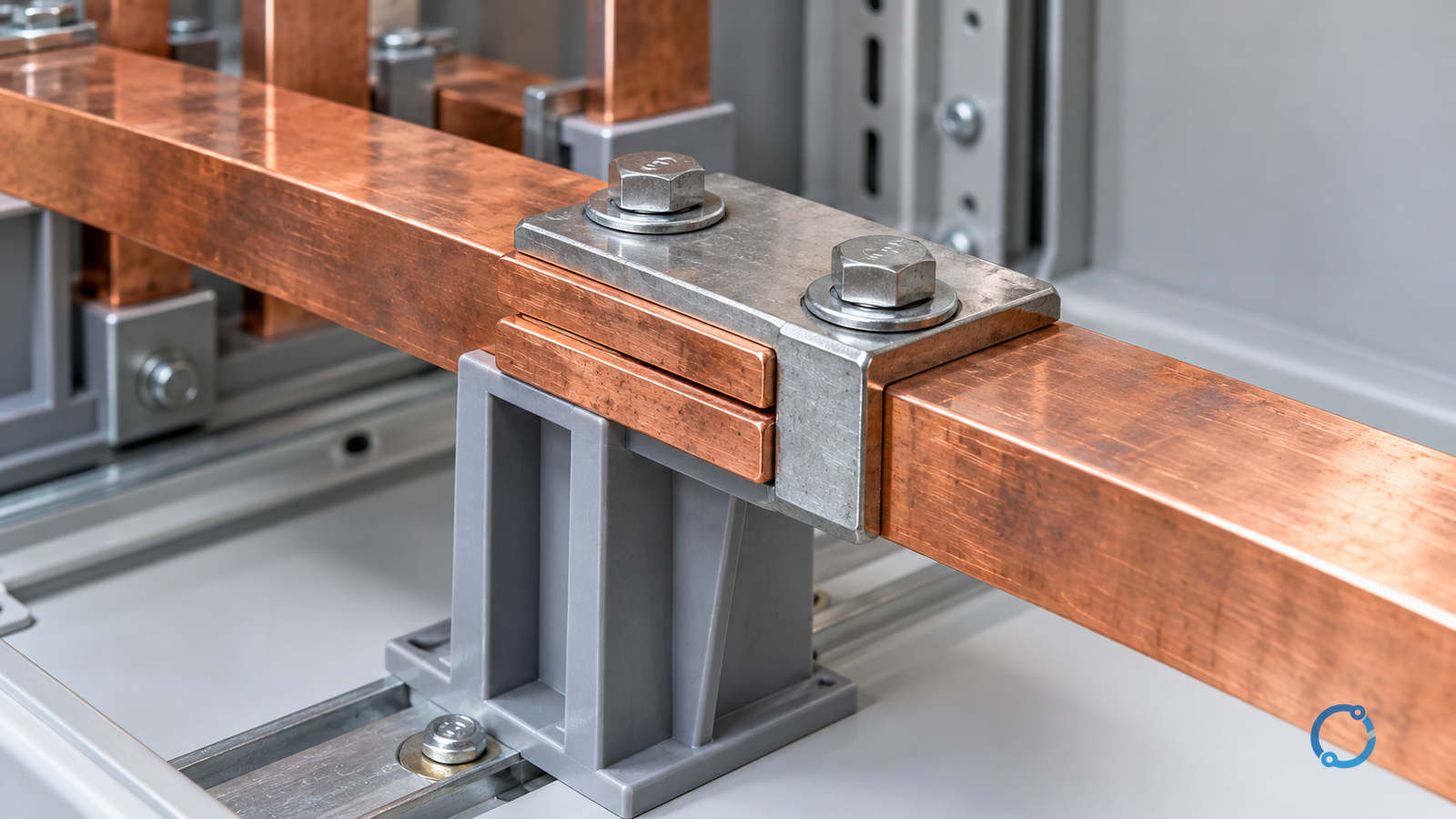
A hot copper busbar joint is not automatically a loose joint. Its temperature is the result of the current it carries, the ambient conditions around it, the heat conducted or radiated from nearby equipment, the condition of the contact surfaces, the clamping force, and the resistance of the complete current path. A thermal image can show that one area is hotter, but it cannot by itself tell you which of those variables caused it.
The safe diagnostic workflow is therefore a sequence of separation, not a search for a single dramatic reading. Confirm the circuit state and load, compare like-for-like phases and similar joints, inspect for visible damage or contamination, check the mechanical condition of the joint, use suitable equipment to verify the electrical path, then isolate and repair before re-energizing. Every step must stay within the qualified-person and local-procedure boundary.
This article is about low-voltage copper busbar joints in enclosed equipment. It does not set a universal temperature limit, torque value, cleaning method, or maintenance interval. Those values belong to the equipment design, the adopted assembly standard, the manufacturer’s instructions, and the site’s approved maintenance procedure.
Start with the safe boundary
Do not open an enclosure, touch a busbar, or place a probe near live parts merely because a thermal image shows a bright area. The U.S. OSHA electrical safety requirements state that live parts to which an employee may be exposed must be de-energized before work, subject to the defined exceptions, and that de-energized parts must be isolated, locked or tagged, and tested by a qualified person before work proceeds. The exact local rules and the site’s electrical safety program still govern.
For this diagnostic task:
- treat every conductor as energized until isolation and verification are complete;
- use only qualified persons for electrical testing and work near exposed parts;
- follow the site’s lockout/tagout, PPE, arc-flash, and energization procedures;
- do not remove covers or guards to improve a thermal view if doing so creates an electrical or mechanical hazard;
- stop and escalate if there is smoke, tracking, a broken support, loose hardware, or visible deformation.
A thermal camera is a diagnostic instrument, not a permission slip. The image is an indirect surface-temperature measurement. Its meaning depends on the camera’s settings, the surface’s emissivity, reflected heat from nearby objects, the viewing angle, focus, distance, and the load at the moment of the image. Record those conditions or the image is not a reproducible observation.
Separate the common cause from the local cause
The first diagnostic fork is whether the heat is common to the whole bus or concentrated at one joint.
| Observation | First question | Useful check | Safe direction |
|---|---|---|---|
| All phases or several joints are hot | Is the load or ambient condition common to them? | Load record, ambient temperature, ventilation, nearby heat sources | Correct load or environment before condemning a joint |
| One joint is hotter under similar current | Does that joint have a different contact path? | Surface condition, hardware, clamping, comparable joints | Plan an isolated inspection and repair |
| One phase is hotter than the others | Is the current different or is the joint different? | Phase-current record and like-for-like joint comparison | Separate electrical imbalance from contact resistance |
| Heat appears only at certain times | Does the duty cycle change the current or the connection? | Trend log, switching record, repeated thermal view | Investigate under a controlled, defined load |
| Heat remains after a repair | Was the repair verified or is another cause present? | Repeat joint check, load record, nearby heat check | Do not close the work on appearance alone |
The table is a reasoning aid, not a threshold table. A hot joint on a lightly loaded circuit and a warm joint on a heavily loaded circuit are different observations. Compare the joint to a similar joint in the same equipment, under the same load and environmental conditions, before treating the temperature difference as a defect.
Record the load and environment first
The current through the joint is the first variable to record. Use the panel’s metering, a suitable clamp meter, or the site’s approved measurement method. Record the phase currents, the time, the load state, and the operating mode. A thermal image taken at one instant is not a load study.
Then record the environment:
- ambient temperature near the enclosure;
- enclosure ventilation and filter condition;
- adjacent heat sources such as transformers, reactors, heaters, or other loaded conductors;
- solar gain or a hot wall if the enclosure is outdoors;
- whether the panel is open, closed, or partially dismantled during the observation;
- the camera’s emissivity setting, reflected-temperature setting, distance, and focus.
The LV switchgear operating-temperature guide provides a wider view of the environmental and load factors that can raise the temperature of an assembly. The copper busbar ampacity and derating guide explains why a nominal current rating is not a complete thermal answer. Use those pages to organize the load and environment record, not to substitute for the equipment’s own limits.
Inspect the joint as a mechanical system
Once the circuit is isolated and verified, inspect the joint for evidence that changes the diagnosis:
- discoloration, pitting, arc marks, melted insulation, or heat damage;
- corrosion, oxidation, contamination, metal filings, or cleaning residue;
- a cracked or deformed support insulator, missing hardware, or a damaged washer;
- a conductor that is not seated correctly or a lug that has moved;
- unequal hardware, incorrect fastener length, or a joint that no longer matches the drawing;
- signs that the joint has been repeatedly tightened without a controlled procedure.
The U.S. OSHA general installation rule requires internal parts, including busbars, wiring terminals, and insulators, to be free from damage or contamination by foreign materials, and it prohibits damaged parts that may adversely affect safe operation or mechanical strength. That is a useful inspection principle: a joint is not acceptable merely because it is still carrying current.
Copper oxide, dirt, and residue can change the contact interface. So can a damaged plating, a burr, or a washer that does not distribute the clamping force as intended. Do not clean or file a contact surface casually. The equipment manufacturer’s instructions and the approved maintenance procedure define the acceptable surface preparation, hardware, and replacement parts.
Understand what thermal imaging can and cannot prove
Thermal imaging is valuable because it scans a large area without contact and can show a temperature difference between comparable joints. It is weak as a standalone root-cause test because it measures surface radiation, not contact resistance. A reflective busbar surface, a nearby hot object, an obstructed view, or a camera setting can change the apparent result.
Use the image to answer three limited questions:
- Where is the suspect area?
- Is the pattern local to a joint, common to a phase, or common to the whole enclosure?
- Does the pattern change with load, time, or a change in ventilation?
Then use an appropriate electrical check to answer the contact-path question. A contact-resistance or voltage-drop measurement can provide evidence about the joint, but the method, instrument, test current, probe placement, and acceptance criterion must be defined for the equipment. A random multimeter reading across a live joint is not a substitute for a controlled test.
IEC TR 60943 provides guidance for estimating permissible temperature and temperature rise of electrical-equipment parts, including contacts, connection terminals, and connected conductors. Its existence does not create one universal acceptance number for every copper busbar joint. The equipment design, the assembly standard, the material, the surface, the current, and the operating environment all affect the permissible result.
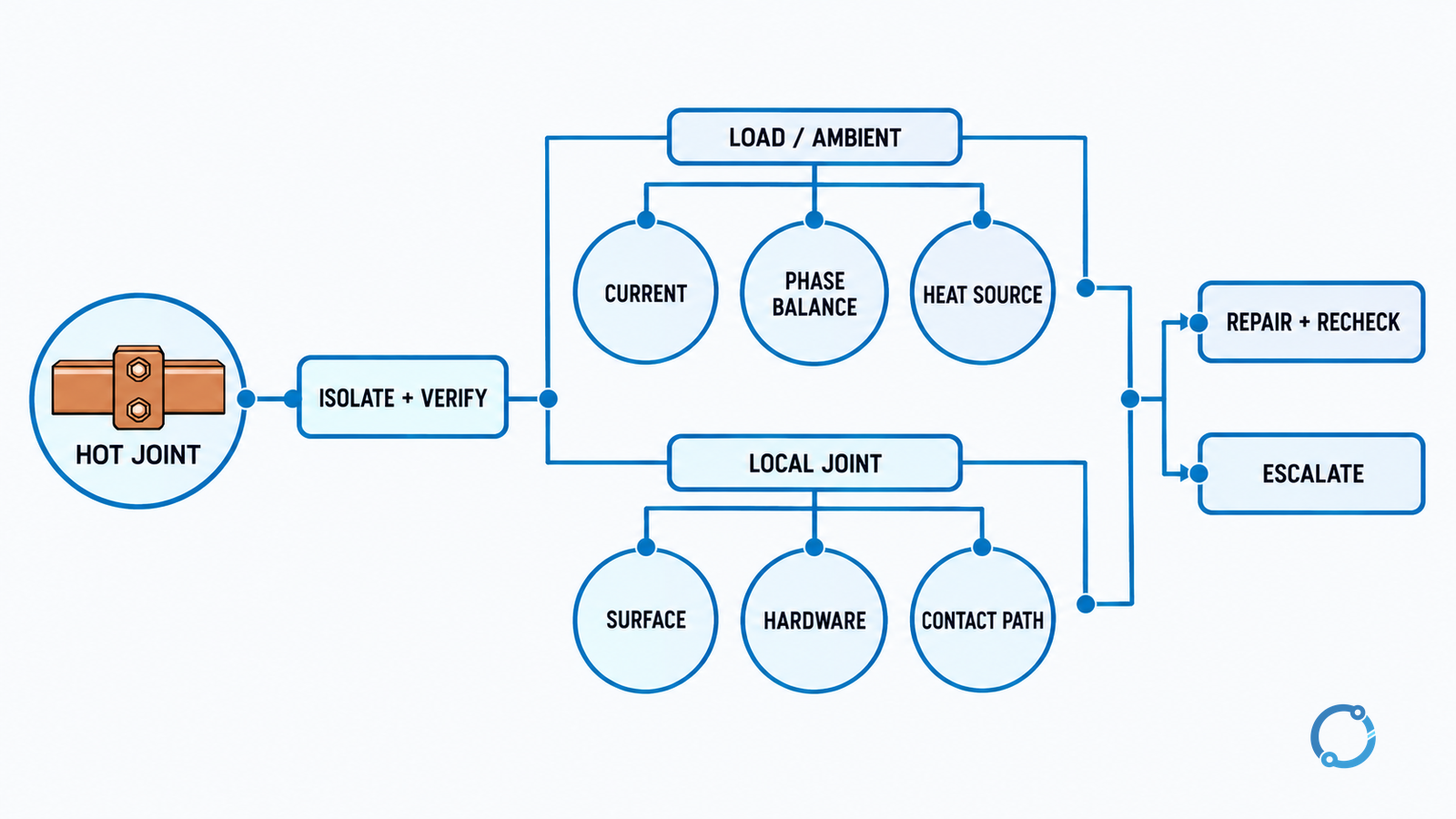
Build a diagnostic tree
Use the following order to keep the investigation reproducible:
- Define the symptom. Record the reported hot spot, the thermal image, the load, the time, and the operating state.
- Check the common cause. Compare phases, parallel paths, similar joints, ambient temperature, and nearby heat sources.
- Check the current basis. Confirm that the joint is carrying the expected current and that the phase balance is understood.
- Inspect the local joint. Look for contamination, damage, incorrect hardware, and support problems after isolation.
- Verify the contact path. Use the approved resistance or voltage-drop method and record the result against a defined criterion.
- Repair the cause. Replace or rework only the hardware and surfaces that the procedure permits; do not assume that tightening alone is a repair.
- Recheck after repair. Repeat the relevant electrical check and, where the procedure allows, a controlled thermal check under a defined load.
- Record and monitor. State the load, ambient conditions, repair, evidence, and any remaining uncertainty.
Step 5 is not optional if the question is contact resistance. A clean-looking joint can still have a poor contact interface. Conversely, a hot joint can be caused by an external heat source or an overloaded bus, so a repair that replaces hardware without addressing the cause can repeat the fault.
Repair, replace or escalate
Repair is appropriate only when the cause is understood and the approved procedure covers the work. Replacement is appropriate when the joint, conductor, insulator, or hardware is damaged beyond the permitted condition. Escalation is appropriate when:
- the equipment is not rated for the measured load or fault environment;
- the joint has arced, melted, or lost mechanical support;
- the correct hardware or surface preparation is unknown;
- the repair procedure requires a manufacturer’s specialist;
- the thermal pattern suggests a system-level load, cooling, or coordination problem;
- the local electrical safety procedure cannot be met.
The busbar short-circuit mechanical stress guide is relevant when the inspection shows deformation, movement, or support damage that may have followed a fault. A thermal symptom is not proof of a short-circuit event, but mechanical evidence changes the investigation. The panel busbar versus terminal-block-and-cable comparison is a useful boundary when the real issue is the distribution architecture rather than one joint.
Recheck the repair under a defined condition
After the repair, do not close the work on a visual inspection alone. Re-establish the guards and covers, restore the approved operating condition, and repeat the checks that the maintenance procedure requires. Record:
- the repair performed and the parts replaced;
- the load and ambient conditions during the recheck;
- the electrical check result against its acceptance criterion;
- the thermal pattern compared with the pre-repair image, if thermal imaging is part of the procedure;
- any remaining temperature difference or uncertainty;
- the date, person, procedure, and next review trigger.
NFPA 70B describes preventive maintenance for electrical, electronic, and communication systems and equipment to prevent failures and worker injuries. That broad scope supports a maintenance record; it does not supply a universal inspection interval or a numeric joint limit. Use the equipment documentation, the assembly standard, and the site’s maintenance program to set those values.
Prevention starts with the design and the record
The best diagnosis is easier when the panel has a usable baseline. Keep the busbar drawing, material and plating specification, joint hardware, support arrangement, design current, fault study, and commissioning records together. A thermal image with no load or ambient record is much less useful than a trend tied to the same operating state.
During installation and maintenance, control the variables that the joint depends on:
- use the specified conductor, plating, hardware, and surface preparation;
- follow the manufacturer’s clamping and replacement instructions;
- protect the joint from contamination and foreign material;
- preserve the specified support and spacing;
- keep the load within the assembly’s verified basis;
- investigate repeated hot spots rather than repeatedly tightening them.
The exact torque, contact-resistance limit, temperature-rise limit, cleaning chemical, and inspection interval must come from the approved documents. Do not copy a number from a generic table into a maintenance procedure without confirming its basis.
A final diagnostic checklist
- The circuit was isolated, locked or tagged, and verified by a qualified person before contact.
- The thermal image has a recorded load, ambient condition, camera setting, and viewing geometry.
- The hot pattern was compared with similar joints and phases under comparable conditions.
- Visible contamination, damage, hardware, and support conditions were recorded.
- The contact-path check used an approved method and a defined acceptance criterion.
- The repair addressed the identified cause, not only the temperature symptom.
- The post-repair check used a defined load and the same measurement basis.
- The result, uncertainty, and next review trigger are recorded.
That workflow will not turn a thermal image into a diagnosis by itself. It will, however, prevent the more common error: replacing a joint before deciding whether the joint, the load, the environment, or the measurement is the real problem.
Sources
- IEC TR 60943:1998+AMD1:2008, permissible temperature rise for electrical equipment parts
- IEC 61439-1:2020, low-voltage switchgear and controlgear assemblies
- NFPA 70B 2026, Standard for Electrical Equipment Maintenance
- 29 CFR 1910.303, electrical installation requirements
- 29 CFR 1910.333, selection and use of work practices
The IEC, NFPA, and eCFR pages were used for public scope and official requirements on 2026-10-23. The full IEC standards are paywalled and were not accessed. The OSHA/eCFR citations are U.S.-specific. No universal joint temperature, torque, contact-resistance, maintenance interval, or product-compliance conclusion is stated.