
High low-voltage (LV) switchgear temperature can come from more internal losses, less heat removal, a hotter surrounding environment, or a localized resistive connection. Diagnose which changed before choosing a corrective action. A single cabinet-air reading cannot distinguish these causes, and there is no universal temperature limit for every point inside every assembly.
This guide helps maintenance and electrical engineers build a comparable evidence record for enclosed industrial LV switchgear. Start with operating records and permitted non-invasive observations. Opening equipment, electrical measurements and repairs require qualified personnel and the applicable safe-work procedure.
First identify what temperature was measured
| Reading | What it represents | What it does not establish |
|---|---|---|
| Room or local external air | A boundary condition around the cabinet | Air temperature at a device inside it |
| Internal cabinet air | Temperature at that sensor position | Every joint, conductor or component temperature |
| Conductor or joint surface | A local surface observation under stated conditions | Internal contact temperature or whole-assembly acceptance |
| Component indication | The quantity defined by its sensor or model | A comparable value unless location and method are known |
Temperature rise is a difference relative to an identified reference, usually expressed in kelvins (K). Absolute operating temperature is normally expressed in degrees Celsius (°C). Do not compare a rise with an absolute limit or use different reference positions as though they were interchangeable.
For each reading, retain its position, method, loading, ambient condition and timing. Infrared results also need appropriate interpretation of surface emissivity and reflections; a bright-metal image is not self-explanatory. See the National Institute of Standards and Technology thermography methodology. Have the qualified thermography specialist document the measurement basis rather than assigning a diagnosis from color alone.
Use a four-cause model
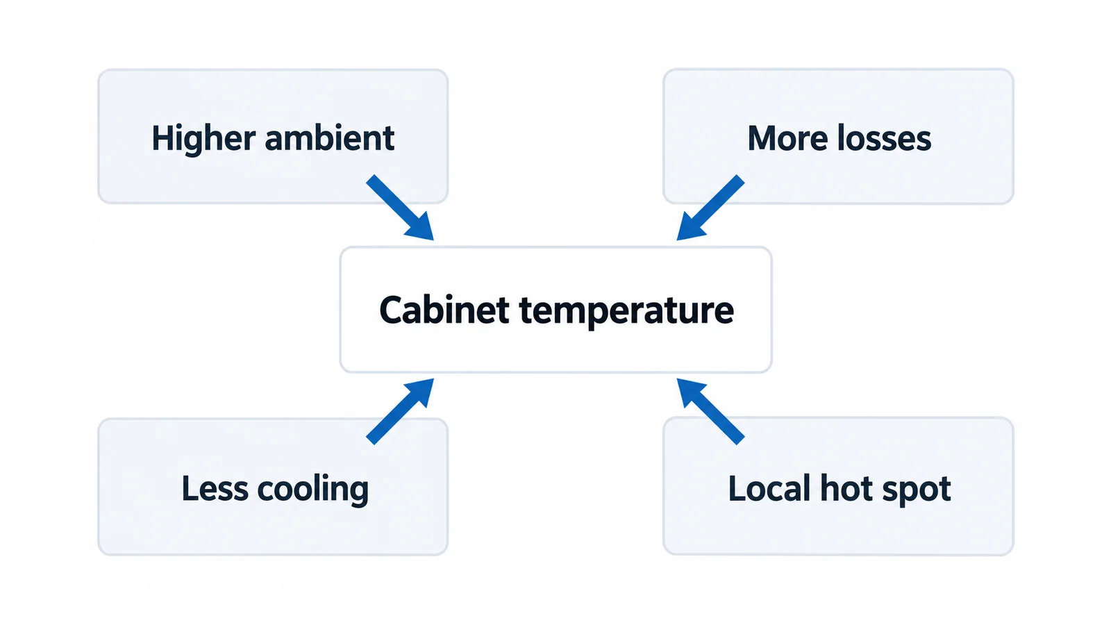
1. More losses inside the enclosure
Load-dependent conductor and connection losses follow I²R, where I is current and R is resistance, when the relevant resistance is held constant. Devices, control power supplies and other equipment can add separate losses. Record changes in current, duty cycle, phase balance and installed equipment instead of assuming all cabinet heat scales with one current reading.
Where waveform or frequency-dependent losses matter, use an appropriate effective-loss model. Where resistance changes with temperature, a constant-resistance estimate is only a sensitivity calculation.
2. Less heat removal
The same losses can produce a different temperature when cooling surfaces, air paths or the enclosure arrangement change. Check the approved layout against obstructions, nearby walls, altered partitions, blocked openings and any fitted cooling equipment’s actual status.
IEC TR 60890:2022, an International Electrotechnical Commission (IEC) technical report, describes an enclosure-air temperature-rise calculation method, primarily for enclosed or partitioned assemblies without forced ventilation. Check its applicability and assumptions; an air-rise estimate does not establish every local component temperature. IEC TR 60890 scope
In US general industry, Occupational Safety and Health Administration (OSHA) regulation 1910.303 includes installation provisions for equipment heat dissipation and unobstructed cooling. That is a jurisdiction-specific reference, not a worldwide cabinet redesign rule. OSHA installation requirements
3. Higher ambient temperature
A room cooling change, adjacent process heat or a changed external environment can move the entire thermal baseline. Compare conditions near the enclosure, not only a distant building sensor. Identify whether the assembly’s accepted ambient conditions still apply.
4. A localized resistive hot spot
A single termination or joint may depart from otherwise comparable neighboring points. That pattern calls for a connection-specific review, not an automatic assumption that the entire cabinet is overloaded. Joint construction and thermal movement matter to maintaining a stable interface. Institutional copper-busbar guide
Do not prescribe energized tightening. The cause may involve interface condition, conductor preparation, loading or mechanical stress; it needs a controlled inspection and the applicable termination instructions. See LV cable terminations for that separate connection task.
Worked loss example: why a 20% current increase is not 44% more total heat
Suppose an enclosure has a hypothetical baseline loss budget:
- Current-dependent losses: 150 W.
- Other losses treated as fixed for this comparison: 85 W.
- Total: 235 W.
If the relevant currents increase by 20%, with the same resistance and duty assumptions:
Current-dependent losses = 150 × 1.20² = 216 W.
New total = 216 + 85 = 301 W, approximately 28.1% above the baseline.
The current-dependent portion rises by 44%, but the total does not because the example contains fixed losses. These invented values illustrate the model; they are not cabinet test results.
The calculation also cannot tell us the new temperature. That requires heat-transfer conditions, loss placement and an applicable model or verification. If the 85 W contribution or ventilation changes too, recalculate the actual budget. For conductor-rating questions, use the separate copper-busbar ampacity and derating guide.
Match the pattern to the next safe check
| Observed pattern | Plausible explanations—not a verdict | Evidence to compare next |
|---|---|---|
| Broad temperature rise alongside higher load | Increased losses; changed duty; cooling no longer adequate | Current/time records, added equipment, ambient and original loss basis |
| Similar load but higher cabinet-air temperature | Higher ambient or reduced heat removal | Comparable external conditions, enclosure surroundings, cooling status |
| One local point departs from equivalent neighbors | Connection-specific resistance or mechanical/termination issue | Repeatable qualified observation, phase loading and isolated inspection plan |
| Upper compartment warmer after a modification | Changed air path, partition or loss location | Approved versus current internal arrangement and sensor positions |
| Temperature rises during repeated short cycles | Time-dependent heat accumulation | Full cycle history, dwell and cooling recovery—not only peak current |
A pattern selects the next check; it does not identify a fault conclusively. If smoke, burning odor, protective operation or another site-defined urgent warning appears, follow the site’s emergency and isolation procedures. Do not continue observation simply to complete this table.
Correct the cause without invalidating the assembly
First establish the assembly’s accepted temperature-rise and operating-condition basis. IEC 61439 general rules apply with the relevant product part; for power assemblies that is typically IEC 61439-2. Component ratings and assembly verification serve different purposes. IEC 61439-1, IEC 61439-2
Adding a fan, cutting an opening or changing a partition is a design change, not a generic maintenance cure. Review its effect on ingress protection, segregation, airflow, fault performance and service access as applicable. Use the responsible assembly designer to establish what evidence must be renewed.
Similarly, increasing copper area is not the first response to every thermal symptom. If layout or conductor design truly needs revision, continue with compact switchgear busbar sizing, which owns that design task.
Any exposed electrical inspection or repair needs the applicable isolation, lockout, absence-of-voltage verification and qualified-person arrangements. OSHA 1910.333 provides a US general-industry example of that work-practice boundary; it does not replace local procedures or authorize energized intervention. OSHA electrical work practices
Close the investigation with a comparable record
Retain sensor positions and methods, load/time history, external conditions, enclosure configuration, original acceptance basis, observed differences and the reason for the corrective action. After correction, compare under defined equivalent conditions and document any unavoidable differences.
The investigation is complete when the temperature change has a supported explanation and an accepted corrective path—not merely when a displayed number falls after the door is opened.
Sources
- IEC TR 60890:2022: public scope of the enclosure-air temperature-rise method.
- IEC 61439-1:2020 and IEC 61439-2:2020: public assembly scopes.
- Copper for Busbars — Guidance for Design and Installation, 2014: physical design principles, not current code limits.
- NIST — Calibration and Measurement Procedures for a High Magnification Thermal Camera: thermography measurement methodology, not a switchgear temperature limit.
- OSHA 1910.303 and OSHA 1910.333: US general-industry installation and work-practice boundaries.