
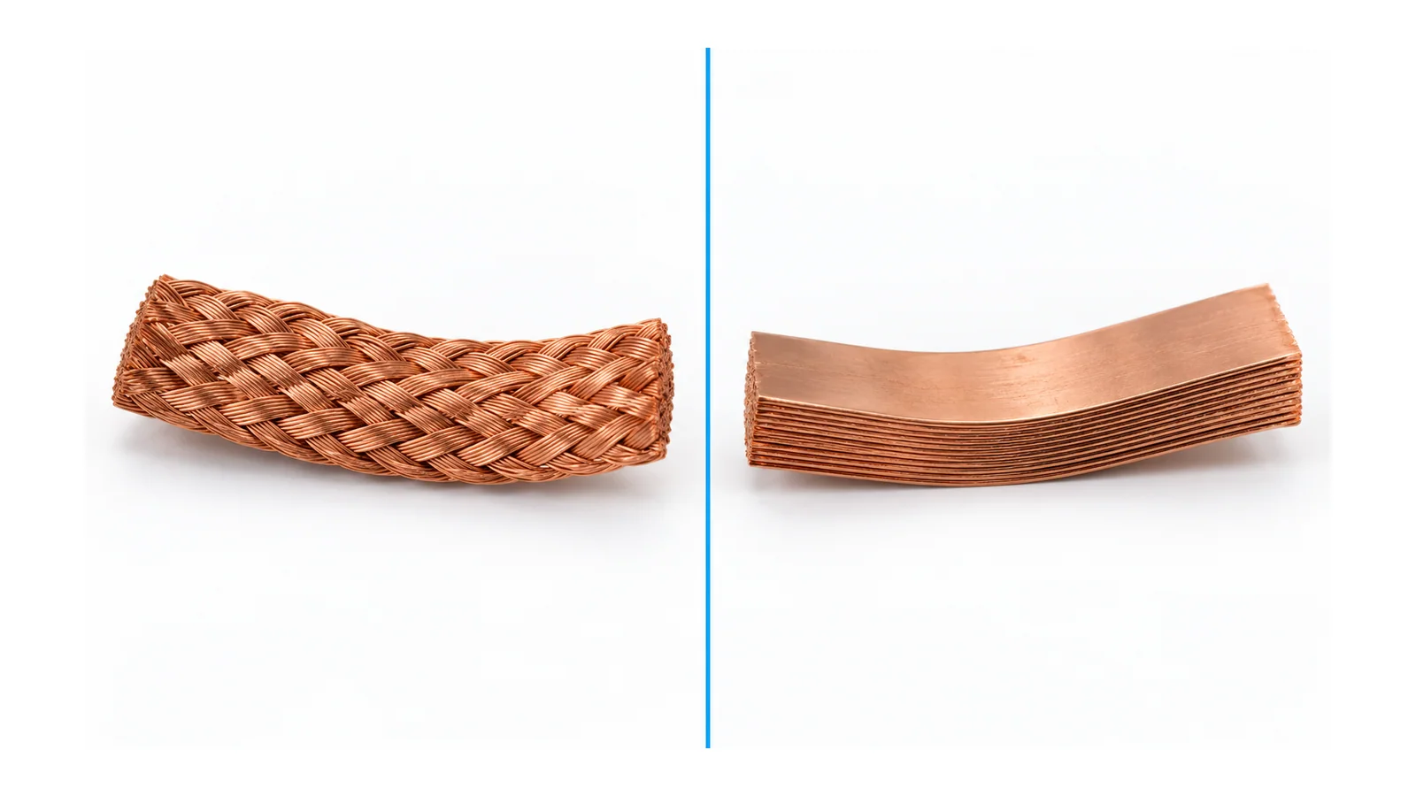
Choose between copper braid and a flexible copper-foil stack by the movement envelope, actual conducting section and end connections, then verify thermal and fault-duty performance in the intended assembly. Neither construction has a universal current-capacity or fatigue-life advantage.
Here, “laminated” means a stack of thin copper foils forming one flexible connection at one electrical potential. It does not mean a multilayer power-electronic bus with separate insulated potentials. This comparison concerns short low-voltage (LV) industrial power links, not a grounding-strap certification or a complete distribution architecture.
Clarify three different meanings before comparing
| Term | Construction meant here | Boundary |
|---|---|---|
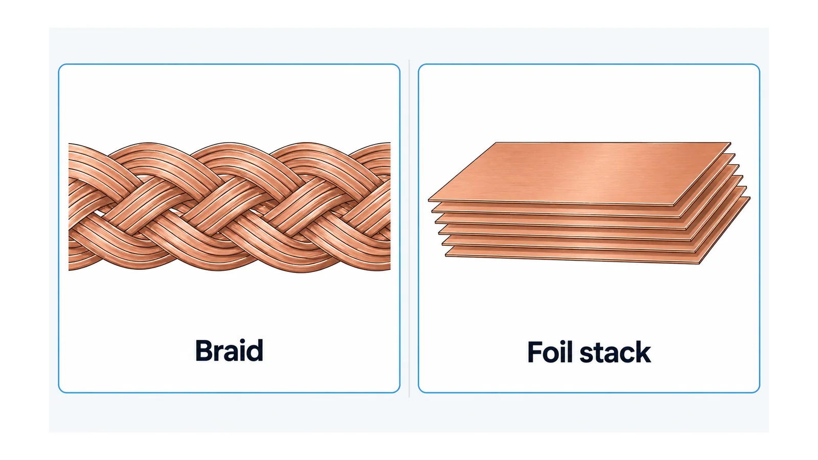
| Braided flexible link | Interwoven copper strands, with engineered end connections | Outer width and thickness include voids and do not directly give net copper area |
| Flexible foil-stack link | Thin copper foils stacked along the flexible section and joined at the ends | Foil layers belong to the same conductive connection; allowable motion is construction-specific |
| Multilayer low-inductance bus | Conductors at different potentials separated by insulation | Geometry of the complete commutation loop matters; it is a different design problem |
Foil and braid are established flexible construction forms, but their appearance is not an electrical qualification. For example, the National Aeronautics and Space Administration (NASA) thermal-strap guide describes both forms for thermal connections; those applications do not establish industrial electrical ratings. NASA construction terminology, section 5.5
For the excluded low-inductance case, Oak Ridge National Laboratory (ORNL) research evaluates the module-and-busbar commutation loop as a system. Do not transfer a low-inductance result to an isolated flexible link merely because it is called laminated. ORNL commutation-loop study For that application boundary, see EV battery busbar design.
Compare the actual motion, not the word “flexible”
Define the installed shape and the movement it must accommodate: direction, displacement, frequency, number of cycles, temperature and loads transferred to the terminals. Occasional forming during assembly is not equivalent to continuous cyclic flexing in service.
Give particular attention to the transition between the flexible section and the consolidated end. Do not assume that movement permitted in the middle is permitted at that transition, or that flexibility in one plane permits twisting in another.
Thermal expansion is one reason flexible elements may be needed. The institutional copper-busbar guide explains how accommodating movement can avoid damaging movement at joints. That principle supports specifying a displacement requirement; it does not provide a generic braid-versus-foil cycle-life ranking. Copper-busbar joint and expansion guidance
A seven-dimension comparison matrix
| Decision dimension | Braided-link question | Foil-stack-link question | Evidence needed for either |
|---|---|---|---|
| Service movement | Is the weave and end transition suitable for the specified motion? | Does the stack accommodate the direction and displacement without unacceptable strain? | Validated motion envelope for the actual construction, environment and cycle duty |
| Conducting section | What is the net metallic section, excluding voids? | What foil section participates in the conductive path? | Declared material, net section and construction details |
| End connection | How are strands consolidated and connected? | How are foils joined and connected at the ends? | Complete termination design and compatible mating interface |
| Installed route | Does the shaped link avoid fouling, abrasion and terminal loading? | Does the formed stack fit without prohibited bending or twisting? | Installed envelope, tolerances and movement clearance |
| Heating | What are link and end losses under the stated conditions? | What are link and end losses under the stated conditions? | Thermal evidence for the complete installed arrangement |
| Insulation and environment | Are insulation, contamination and exposure requirements resolved? | Are insulation, contamination and exposure requirements resolved? | Insulation-system and environmental suitability, including ends |
| Fault restraint | Can supports and ends withstand the specified fault duty? | Can supports and ends withstand the specified fault duty? | Assembly-level mechanical and short-circuit evidence |
These questions deliberately do not award a winner by construction name. A well-qualified candidate of either form can be better suited than an inadequately documented candidate of the other.
Equal envelope size is not equal copper section
For a hypothetical straight foil stack with 12 foils, each 25 mm wide and 0.20 mm thick:
Net copper area = 12 × 25 × 0.20 = 60 mm².
This is a geometric sum, not an ampacity calculation. It assumes all stated foils are copper and participate in the section. It does not establish end-contact performance or operating temperature.
For braid, multiplying outer width by outer thickness counts air gaps as if they were copper. Use the actual net metallic section declared for that construction, not its external envelope. Conversely, equal net copper area does not prove equal link resistance, end loss, thermal behavior or movement capability.
Use the copper-busbar ampacity and derating guide for the separate conductor-capacity task. Do not convert the 60 mm² example into an unsupported current rating.
Compare complete-link resistance under equivalent conditions
Suppose two hypothetical candidate links, including their ends, have effective resistances of 20 µΩ and 30 µΩ under the same stated conditions. At 600 A:
- Candidate A loss = 600² × 20 × 10⁻⁶ = 7.2 W.
- Candidate B loss = 600² × 30 × 10⁻⁶ = 10.8 W.
These are invented inputs illustrating I²R, not measurements and not a braid-versus-foil ranking. For alternating-current (AC) duty, the resistance input must represent the relevant effective losses; a direct-current (DC) resistance comparison alone may be insufficient.
Also separate resistance from cooling. Lower calculated loss does not automatically mean lower temperature at every point if surface conditions, insulation, placement or contact interfaces differ. Specify the test or calculation conditions and assess the actual installed link and mating joints.
Connection preparation, contact pressure and mechanical compatibility remain essential. For the broader termination boundary, see LV cable terminations; do not treat cable-lug instructions as a universal busbar-end specification.
Do not trade flexibility for unresolved fault behavior
A flexible link still conducts fault current and can experience mechanical forces. Its end connections, supports, clearances and restraints belong to the assembly design. Neither a motion demonstration nor a nominal conductor-area match establishes that behavior.
IEC 61439-2, from the International Electrotechnical Commission, covers power switchgear and controlgear assemblies. Use the applicable assembly verification basis to resolve the proposed configuration; the public standard scope does not certify a particular connection. IEC 61439-2 scope
There is also no universal bend radius in this comparison. Obtain the construction-specific forming and service-motion limits. If the route cannot meet them, change the route or construction; do not assume a softer-looking link removes the requirement.
The selection record: accepted, rejected or unresolved
For each candidate, retain the same endpoint geometry, electrical duty, ambient conditions and movement requirement. Record net copper section, complete termination details, allowed forming/service motion, thermal evidence, insulation boundary and fault restraint.
Then classify each decision dimension as accepted, rejected or unresolved. An unresolved cyclic-motion claim or unverified end connection is a reason to withhold acceptance, not to fill the gap with a generic material comparison.
The result may favor braid, foil stack, or neither candidate. The defensible answer is the construction whose complete installed connection satisfies the stated duty with adequate evidence.
Sources
- NASA Passive Thermal Control Engineering Guidebook, Rev.5.1, section 5.5: foil/braid construction terminology only, not electrical qualification.
- ORNL — Commutation-loop inductance study: system-loop boundary for the separate power-electronic bus problem.
- Copper for Busbars — Guidance for Design and Installation, 2014: joint and thermal-movement principles.
- IEC 61439-2:2020: public assembly scope.