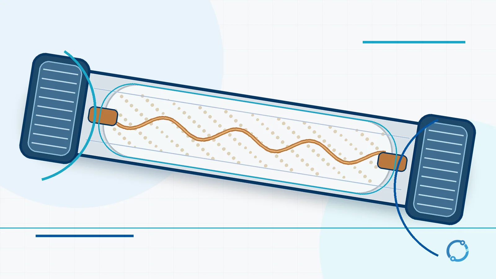
A fuse is a one-time overcurrent protective device built around a deliberately sacrificial conductor. The fuse element is connected in series with the circuit and carries normal current without melting. When current rises above the range the fuse is designed to accept, the element heats faster than its body can dissipate the energy, reaches its melting point and opens the current path. The resulting arc must also be controlled and extinguished before the circuit is truly interrupted.
That definition separates a fuse from a switch, a circuit breaker and a residual-current device. A fuse does not decide when to open through a motor, spring or electronic trip unit. Its response comes from the physical heating of the element and the designed time-current characteristic. It is also not reusable: after operation, the element has been destroyed and the fuse must be replaced with a correctly rated device after the cause has been found.
The useful question is therefore not only “what is a fuse?” but “what is this fuse expected to protect, and what fault current can it safely interrupt?” The answer depends on the complete circuit, not on the fuse body alone.
A controlled weak point in the current path
Every conductor has resistance. Current through that resistance produces heat, and the rate of heating is related to current squared:
P = I^2R
where P is power dissipated in the element, I is current and R is the resistance of the element. The formula explains the basic principle, but it does not by itself predict when a particular fuse will operate. Heat storage, element geometry, surrounding material, contact conditions and the fuse’s designed time-current behaviour all affect the result.
That is why a fuse element is not simply a thin wire chosen by eye. It is a calibrated part of a protective device. At normal current, the heat produced should remain within the design limits of the element and body. During an overcurrent, the heat input rises much faster than the current. If the current doubles while resistance is treated as fixed for this comparison, the heating rate becomes four times as large:
(2I / I)^2 = 4
If the current triples, the heating rate becomes nine times as large:
(3I / I)^2 = 9
These ratios explain why a severe short-circuit current can melt an element much more quickly than a modest overload. They do not give a universal clearing time. Two fuses with the same nominal current can be designed with different element shapes and thermal behaviour, so timing must come from the specific time-current curve and the conditions stated by its manufacturer.
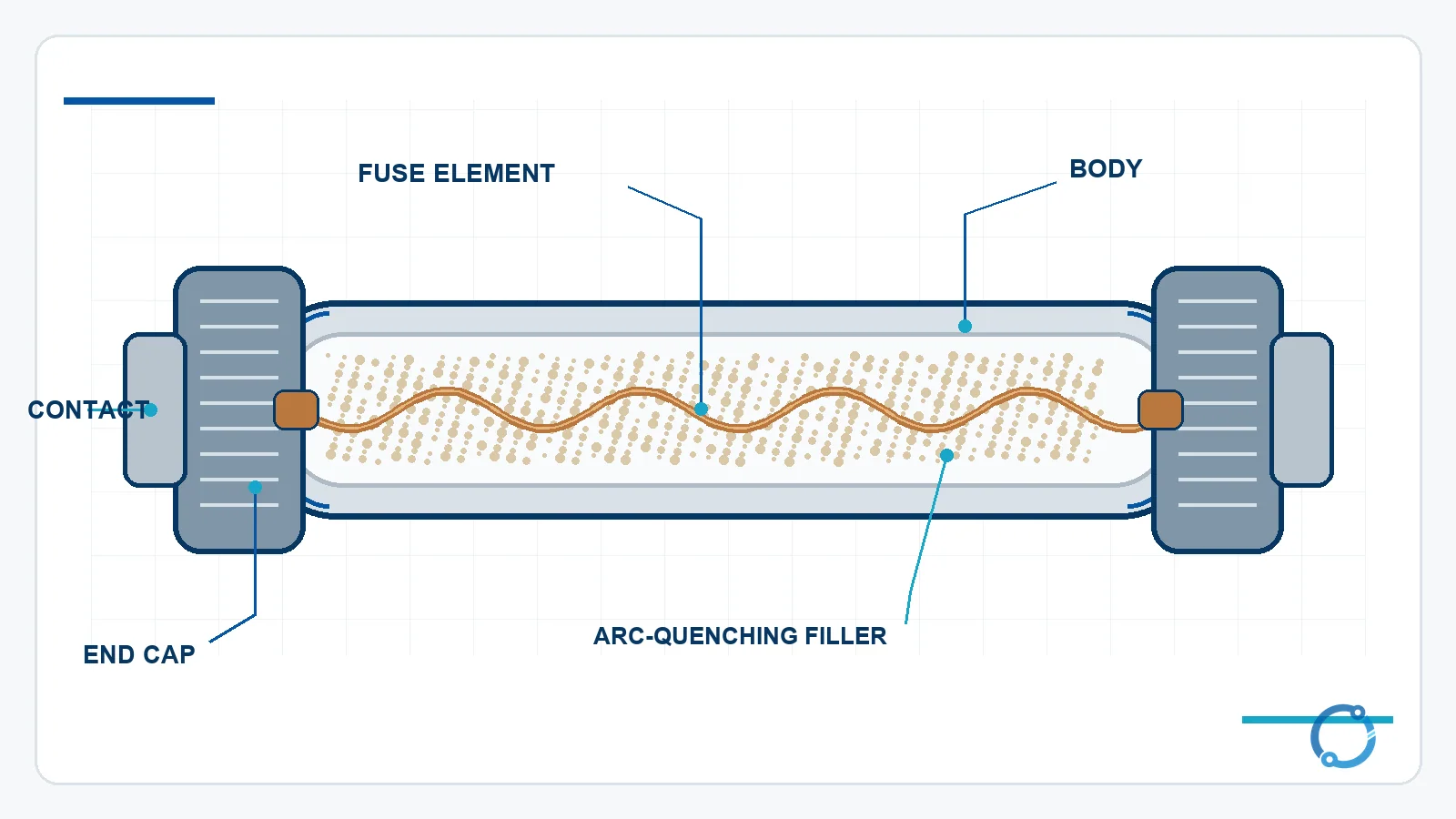
The physical parts of a fuse
A fuse is mechanically simple, but each part has a protective role rather than a decorative one.
Fuse element
The element is the calibrated conductor that melts when the protected circuit draws excessive current. Its material, cross-section, length and shape influence resistance, heat distribution and opening behaviour. A reduced section can create a local hot spot, while a more elaborate element shape may be used to influence arc behaviour.
Body or housing
The body contains the element, filler and internal pressure that develops during interruption. A common industrial form uses a sturdy ceramic or insulating tube, while smaller fuses may use glass or another molded body. The body must be treated as part of the fuse’s design, not as generic packaging that can be cracked or repaired.
Arc-quenching filler
Many cartridge fuses surround the element with a granular filler such as silica sand. When the element melts, the filler can help absorb energy, cool the arc and support rapid transition to a high-resistance state. The exact construction is design-specific. The important point is that interrupting a fault is not only a matter of breaking a wire; the fuse must also manage the arc that follows.
End caps and contacts
The end caps connect the internal element to the fuse contacts and current path. Poor contact pressure, corrosion or an unsuitable holder can create extra heat that has nothing to do with the element’s calibration. A fuse that looks correctly rated can still overheat because its holder or termination is unsuitable.
How an overcurrent becomes an open circuit
The process can be divided into three practical stages.
1. Current raises the element temperature
The element is part of the circuit, so load current passes through it. At normal current, the heat generated is intended to stay below the level that would compromise the element. When an overload or short-circuit current appears, the additional heating raises the element temperature toward its melting range.
2. The element melts and an arc forms
Melting alone does not necessarily establish an immediate open circuit. As the metal separates, the changing current path can create an arc. The fuse must control that arc, increase its resistance and extinguish it within the conditions for which the fuse is rated. The body, filler, element geometry and internal pressure all contribute to that process.
3. The circuit is cleared and the fuse remains open
After successful interruption, the fuse element is no longer a continuous conductor. A multimeter or voltage test may show that the path is open, but appearance alone is not enough for a maintenance decision. An opened fuse is evidence that something exceeded its intended operating condition or that the fuse, holder or circuit was unsuitable.
The distinction between overload and short-circuit current matters. An overload may develop over seconds or minutes, depending on the current and fuse characteristic. A high available short-circuit current may produce rapid element melting, but the fuse must still have an adequate breaking capacity for the circuit’s prospective fault current. “It melts quickly” is not the same as “it can interrupt the fault safely.”
The four ratings that must agree with the circuit
A fuse is often discussed through its current rating alone. That is incomplete. A safer reading treats four ratings as a set.
| Rating | What it describes | What can go wrong when it is misunderstood |
|---|---|---|
| Rated current | The current the fuse is designed to carry under its specified conditions. | Changing to a larger value may stop repeat operation while leaving the conductor or equipment inadequately protected. |
| Rated voltage | The voltage range for which interruption is intended. | A fuse used outside its voltage basis may not control the arc safely, even if its current rating looks suitable. |
| Breaking or interrupting capacity | The maximum fault current the fuse is designed to interrupt under the applicable conditions. | A fuse that melts but cannot contain the fault energy may fail to clear the circuit safely. |
| Time-current characteristic | The relationship between current magnitude and operating time for the fuse design. | A fast fuse may react to harmless inrush, while an unnecessarily slow fuse may not protect a sensitive device as intended. |
Rated current is not a target
The marked current is not a value the designer should try to maximize. It must coordinate with the conductors, equipment, ambient conditions, enclosure, holder, terminations and expected load profile. A fuse must carry the intended current without nuisance operation while still protecting the weakest part of the circuit.
For AC loads, current may also depend on real power and power factor. That relationship is why a load’s kilowatt rating cannot always be converted directly into a fuse current without checking the circuit voltage and operating power factor. OHELE’s explanation of power factor covers that separate calculation concept.
Rated voltage is an interruption condition
A fuse must not be treated as a wire that happens to have a voltage printed on it. The voltage rating belongs to the fuse’s ability to interrupt the circuit under specified conditions. Using a low-voltage fuse on a higher-voltage system is not a valid shortcut, even if the normal load current is small.
Breaking capacity is part of safety
The available fault current at an installation can be much higher than normal load current. The fuse must be able to interrupt the maximum prospective current at the applicable voltage without bursting, failing or leaving an unsafe arc path. A device that opens under a small overload is not automatically suitable for a high-energy short circuit.
The curve controls timing
The time-current curve is the part of the rating story that converts the mechanism into a design tool. It shows that a fuse has a characteristic rather than one fixed tripping current. The curve must be read together with voltage, breaking capacity, ambient conditions and the protected equipment’s withstand capability.
Fast-acting and time-delay fuses
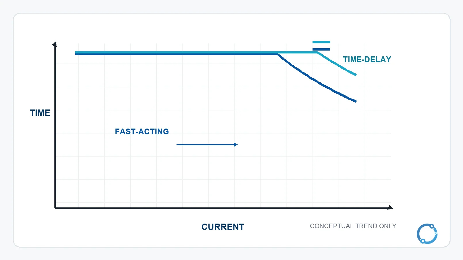
Fuse timing is a balance between protection and tolerance for expected temporary current.
Fast-acting fuses
A fast-acting fuse responds quickly to overcurrent and is commonly used where rapid isolation is important or where short-duration high current is not a normal operating event. Semiconductor protection is a common conceptual example: the protected device may have limited tolerance for fault energy, so the protective characteristic and its coordination must be selected carefully.
Time-delay fuses
A time-delay fuse is designed to ride through some short-duration inrush without opening while still responding to a sustained overload or fault. Motors, transformers and capacitor circuits can create current that is much higher than normal running current for a brief period. A fuse selected only by the word “slow” is not enough. The curve, the expected inrush and the circuit’s protective coordination must all be checked.
Fast-acting does not mean “better” and time-delay does not mean “safer.” The correct choice depends on the load, the available fault current, the protected component and the required interruption performance. The same principle applies when a fuse is considered alongside a breaker or another protective device. The comparison is a coordination question, not a simple race.
Main fuse types
Fuse families use different bodies and contacts because they serve different installation environments. The following overview deliberately avoids current ranges and model-specific ratings because those values vary by product and standard.
| Type | Basic form | Typical role |
|---|---|---|
| Glass or ceramic cartridge | Cylindrical body with end contacts; the element is enclosed inside. | General control, small equipment and conventional low-voltage circuits, depending on the marked fuse and holder. |
| Automotive blade | Flat insulating body with two blade contacts and an enclosed element. | Vehicle branch circuits, with the correct voltage and current basis required by the application. |
| High rupturing capacity (HRC) | Robust cartridge designed for high available fault current and controlled arc interruption. | Industrial distribution and equipment protection where fault level and breaking capacity matter. |
| Semiconductor protection | Fast fuse construction intended for equipment with limited fault tolerance. | Rectifiers, converters and other semiconductor circuits, subject to the specific fuse standard and coordination study. |
| Medium-voltage fuse | Fuse link and holder system intended for the applicable medium-voltage equipment. | Transformer, capacitor and feeder protection within a defined medium-voltage design. OHELE discusses the separate rating framework in medium-voltage fuse ratings. |
A high rupturing capacity fuse is not a universal upgrade for every circuit. The holder, voltage rating, current rating, curve and equipment approval must all match. Likewise, a small glass or plastic-bodied fuse is not automatically suitable for a high-energy industrial circuit. The construction family is a starting point, not a selection decision.
Fuse versus circuit breaker
The essential boundary is that a fuse is a sacrificial device and a circuit breaker is intended to be reset after an operation. A fuse opens by melting its element; a breaker uses a mechanism to separate contacts and includes some means of trip and reset. Either can be suitable for a given circuit, but the choice depends on the coordination, available fault current, load behaviour, operating procedure and verification requirements of the installation. OHELE’s fuse versus breaker comparison covers the selection workflow; this page does not repeat that comparison table.
Three common misunderstandings
“Install a bigger fuse so it stops blowing”
A fuse that repeatedly opens is sending a message about the circuit. Increasing the current rating may hide the symptom while allowing a conductor, contact, load or protected component to overheat. The replacement must match the original equipment design and the fault must be investigated. The correct current is the one supported by the circuit and protective coordination, not the largest value that survives a short trial.
“A fuse protects people from electric shock”
A fuse is an overcurrent device. It does not detect a small leakage current, an exposed enclosure or a person becoming part of a fault path. Equipment grounding and residual-current protection address different hazards. OHELE’s explanation of grounding and earthing provides the system-level boundary, but no article can replace local electrical safety procedures.
“If it is rated correctly, any fuse of the same size will do”
Physical fit does not prove electrical equivalence. Two fuses can share a body size while differing in voltage rating, breaking capacity, time-current behaviour, utilization category or intended equipment type. The replacement should be verified from the equipment marking, fuse marking, approved documentation and the circuit function, not from appearance.
What to check before replacement
Before a fuse is touched, the equipment should be placed in a safe state under the site’s electrical safety procedure. That normally includes isolation, lockout or tagout, and verification that the relevant conductors are de-energized with an instrument suitable for the installation. A blown fuse is not permission to work energized.
After isolation, the maintenance task should establish four things:
- The fuse is the specified type and current rating for that holder and circuit.
- The voltage basis and breaking capacity are suitable for the installation.
- The holder, contacts and terminations are not damaged or overheating.
- The cause of the operation has been addressed, not merely removed.
If the replacement selected by the maintenance team is not the exact equipment-approved type, a qualified person should review the change against the circuit’s protection and coordination requirements. A related breaker-sizing method is outside the scope of this definition page; readers can use the circuit-breaker sizing calculation guide only as a starting point for the broader coordination question. The electric current fundamentals page explains the current quantity that every fuse rating is intended to control.
Frequently asked questions
Does a fuse protect against electric shock?
No. A fuse is designed for overcurrent protection. It may clear a fault that creates a large current, but it does not detect small leakage current or prevent contact with a live part. Grounding, equipotential bonding and residual-current devices address different protective functions and must be applied according to the installation’s design and local requirements.
Can I replace a fuse with a higher current rating?
Do not do so unless the equipment design and qualified protection review show that the higher rating remains valid. A larger fuse may pass more current than the conductors, contacts or downstream equipment can safely carry. It can also change discrimination and damage coordination. The correct response to repeated opening is to identify the cause and verify the specified replacement.
What does breaking capacity mean on a fuse?
Breaking capacity, also called interrupting capacity in some contexts, describes the maximum fault current the fuse is designed to interrupt under its specified conditions. A fuse used where the available fault current exceeds that capability may not clear the fault safely. The marked rating must be read within the voltage and standard basis that applies to the product.
Why did a new fuse open immediately?
An immediate opening can indicate a persistent short circuit, a failed component, incorrect wiring, an unsuitable fuse or a damaged holder. It is not a reason to keep increasing the current rating. Isolate the circuit, use the equipment documentation and test the fault path under the site’s safe-work procedure. The cause must be corrected before another replacement is energized.
How can I tell a fast-acting fuse from a time-delay fuse?
Use the fuse marking, manufacturer’s time-current curve and the equipment’s approved replacement information. A visual size or glass-versus-ceramic difference is not enough. Fast-acting and time-delay designs can share a similar external form while behaving differently. The required choice depends on expected inrush, sustained load, fault level and the protected equipment’s tolerance.