Short answer: Power factor is the ratio of real power to apparent power, PF = P / S. Under sinusoidal voltage and current, it also equals cos(phi), where phi is the phase angle between them. Power factor is dimensionless and, using the usual magnitude-oriented meaning, ranges from zero to one. A lagging power factor describes current that reaches corresponding points later than voltage; a leading power factor describes current that reaches them earlier.
That one ratio helps explain why a load rated at 10 kW can require 12.5 kVA from the source. The missing difference is not energy that disappears. It is the extra capacity associated with reactive power that oscillates between electric and magnetic fields. Power factor describes how effectively the source current is aligned with the voltage for delivering active power.
This is a definition and calculation page. It explains the three power quantities, lagging and leading current, and the principle of shunt-capacitor correction. Capacitor-bank design, switching control and equipment selection belong to separate engineering tasks and separate OHELE guides.
Power factor in one equation
IEC vocabulary defines power factor under periodic conditions as the ratio of the absolute value of active power to apparent power. With sinusoidally varying voltage and current, it is often written as:
PF = P / S = cos(phi)
Here:
Pis active, real or average power in watts.Sis apparent power in volt-amperes.Qis reactive power in reactive volt-amperes, or var.phiis the phase displacement between sinusoidal voltage and current.
The distinction between watts and volt-amperes matters. A piece of equipment may perform 10 kW of useful work while drawing 12.5 kVA. If the reader treats the two units as interchangeable, the extra current and the need for reactive-power management become invisible.
This definition is most straightforward for a stable sinusoidal system. Distorted current adds another consideration: the total power factor can be influenced by waveform distortion as well as phase displacement. That difference is discussed later.
Real, reactive and apparent power
Real power
Real power is the average rate at which energy is transferred in one direction and does useful work or produces heat. It is measured in watts. A motor produces shaft work, a heater releases heat and a lamp emits light and heat. Those useful outcomes are associated with real power.
Real power is not automatically the same as every watt lost or consumed. It is the component associated with energy transfer averaged over a cycle. The difference between kW and kWh matters when energy over time is the question rather than the instantaneous or average power demand.
Reactive power
Reactive power is associated with energy exchanged between a source and the electric or magnetic fields of a load. It is measured in var, with practical quantities often expressed in kvar. In an inductor, current is building a magnetic field during part of the cycle and the field returns energy during another part. In a capacitor, the electric field performs the analogous exchange.
Reactive power does not, by itself, transfer net energy to the mechanical output. It still matters because the source, cables, transformers and switches must supply the associated current. It also determines the phase displacement between voltage and current for an ideal linear reactive element.
Apparent power
Apparent power is the product of voltage and current magnitudes when the phase relationship is included. It is measured in volt-amperes or kilovolt-amperes. For sinusoidal conditions:
S = V_rms x I_rms
Apparent power is the total capacity the supply interface must handle. For P = 10 kW and PF = 0.8, the apparent power is 12.5 kVA. The equipment current corresponds to 12.5 kVA, not merely to the real-power number.
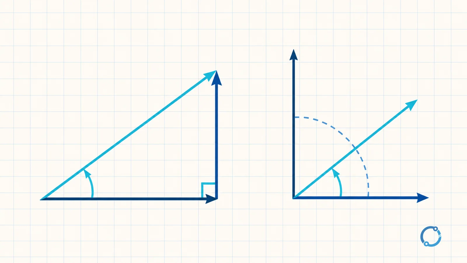
The three quantities form a right triangle only for the sinusoidal case used in this article:
S^2 = P^2 + Q^2
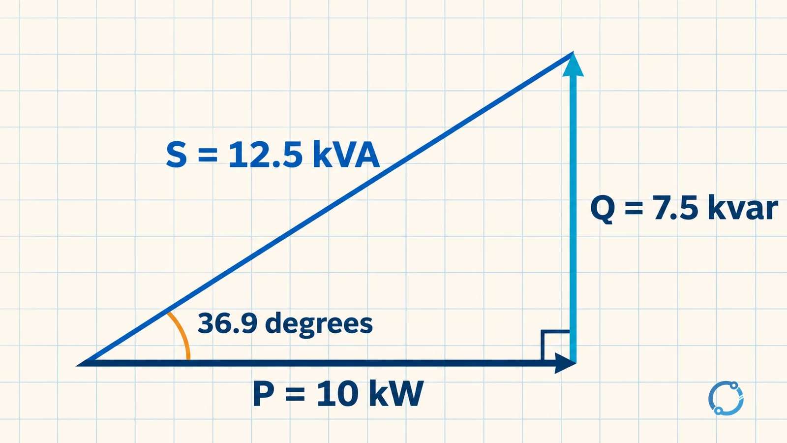
That relationship is a calculation tool, not a claim that every distorted or multiphase system can be represented by one simple scalar triangle. It applies within the clearly stated sinusoidal assumptions.
Where the phase difference comes from
Resistive load
An ideal resistor has voltage and current in phase. When voltage reaches a positive peak, current reaches its positive peak at the same moment. The phase angle is zero, so PF = cos(0) = 1. All supplied apparent power is real power.
Real equipment is rarely a perfect resistor. A heater may have small inductance, a cable has resistance and capacitance, and a power supply may draw a distorted current. The ideal resistor is still useful for understanding the boundary.
Inductive load
An ideal inductor has current lagging voltage by one quarter cycle. The current reaches its positive peak later than the voltage. The magnitude-oriented power factor is zero because the net real power over a complete sinusoidal cycle is zero, even though energy moves into and out of the magnetic field each half cycle.
Many motors, transformers and magnetic devices behave inductively over part of their operating range. Their current typically includes a real-power component and a lagging reactive component. The relationship between voltage, current and resistance is useful for understanding the resistive part, but it does not by itself describe a reactive load.
Capacitive load
An ideal capacitor has current leading voltage by one quarter cycle. The current reaches its positive peak earlier than the voltage. Its ideal sinusoidal power factor is also zero in magnitude, although the sign convention used to describe reactive power may differ among texts.
Capacitors are often connected in parallel with inductive equipment to supply reactive current locally. The combination of an inductive load and a capacitor bank can bring the source-side current closer to the voltage waveform.
The ideal boundaries
For the sinusoidal magnitude convention:
- A pure resistor has
PF = 1. - A pure inductor has
PF = 0. - A pure capacitor has
PF = 0.
Real loads lie between those ideal boundaries or may have power factor affected by waveform distortion. A motor does not become a pure inductor, and a capacitor bank does not correct every cause of poor power factor.
Lagging versus leading
Lagging and leading describe the direction of phase displacement; they are not quality labels by themselves.
| Condition | Current relative to voltage | Common source of the behavior | Reactive-power convention in many power texts |
|---|---|---|---|
| Lagging | Current reaches corresponding points later | Inductive motor, transformer or magnetic load | Positive Q for an inductive load |
| Leading | Current reaches corresponding points earlier | Capacitive compensation or a dominantly capacitive circuit | Negative Q for a capacitive load |
| Unity | Current and voltage are in phase | Ideal resistor or a compensated condition at the measurement point | Zero reactive-power component |
The sign convention is not universal. Some power-quality instruments and technical documents use the opposite sign for delivered or absorbed reactive power, and a few use labels that depend on the metering direction. The physical meaning remains important: identify whether current is leading or lagging at the measurement point and state the convention used.
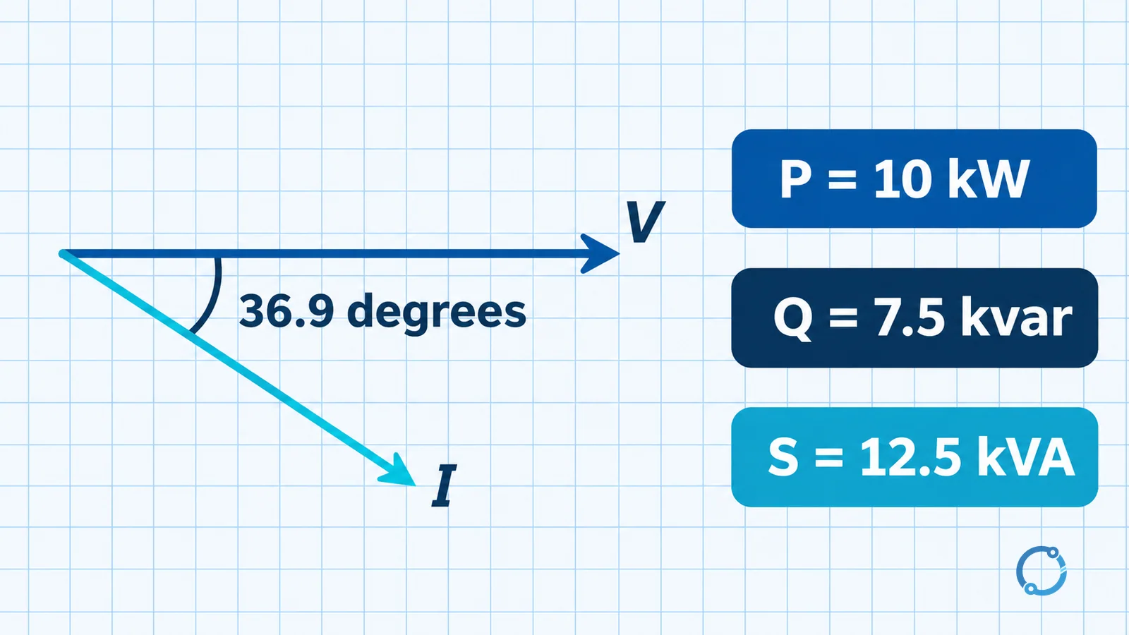
Worked example: 10 kW at 0.8 lagging
Consider a hypothetical load with a real-power demand of 10 kW and a lagging power factor of 0.8. The values are teaching inputs, not a product rating or a survey result.
Find apparent power
S = P / PF
S = 10 kW / 0.8 = 12.5 kVA
The source and current-carrying equipment must accommodate 12.5 kVA of apparent power for the same 10 kW of real power.
Find reactive power
Use the sinusoidal power-triangle relationship:
Q = sqrt(S^2 - P^2)
Q = sqrt(12.5^2 - 10^2) = sqrt(156.25 - 100) = sqrt(56.25) = 7.5 kvar
The load therefore has a 7.5 kvar reactive component under the stated ideal sinusoidal model.
Find the phase angle
phi = arccos(PF) = arccos(0.8)
phi = 36.9 degrees when rounded to one decimal place.
The rounded angle and the original values remain consistent within display precision. cos(36.9 degrees) = 0.7997, which rounds to 0.8.
Why a low power factor matters
At PF = 1, a 10 kW load would require 10 kVA for the stated ideal calculation. At PF = 0.8, it requires 12.5 kVA. The apparent-power ratio is:
12.5 / 10 = 1.25
That is 25 percent more apparent power for the same real power. If voltage is held approximately constant, current is proportional to apparent power, so the current is also about 25 percent higher.
That extra current has practical consequences without inventing a billing rule. Conductor heating depends on current, so losses increase with current for a given conductor resistance. Transformers, generators, cables and switchgear must be applied within their own current and temperature limits. Voltage drop may also increase. The exact financial treatment depends on tariffs, contracts and local regulation and is outside this definition page.
Power factor is not simply another name for efficiency. Efficiency compares useful output with total input and is commonly expressed as a percentage. Power factor compares real power with apparent power and is dimensionless. A load can be efficient while still drawing a lagging current, or inefficient while having a unity displacement factor at a particular operating point.
Raising power factor with shunt capacitors
The principle of correction is to supply some or all of the load’s inductive reactive demand locally. A capacitor produces leading reactive current that opposes the lagging reactive current of the inductive load. The source then needs to supply less reactive power, so its current moves closer to the voltage waveform.
Continue the example. Suppose the goal is to change the magnitude of power factor from 0.8 to 0.95 while holding the same 10 kW real power and assuming a sinusoidal system. First find the reactive power corresponding to 0.95:
Q_new = P x tan(arccos(0.95))
Q_new = 10 x tan(18.19 degrees) = 3.29 kvar when rounded.
The amount of reactive power to add is the difference between the original and target reactive values:
Q_add = 7.5 - 3.29 = 4.21 kvar
The result is approximately 4.2 kvar. This is a teaching calculation, not a capacitor order. A real correction stage requires voltage verification, harmonics assessment, switching duty, protection, discharge and resonance studies, plus manufacturer data for the selected capacitor equipment.
The functional location of a capacitor bank is shown in the capacitor-bank panel diagram. If the correction objective is already established, capacitor microfarads to kvar explains the conversion. Power-factor relay wiring on LV and MV systems covers measurement and control architecture rather than repeating it here.
Three common misreadings
Power factor is not efficiency
Power factor describes the phase relationship between voltage and current and the ratio of real to apparent power. Efficiency describes how much useful output results from input energy. The quantities may both be important, but they cannot be substituted for one another.
Power factor of one does not mean no reactive exchange
A source-side power factor of one means the net voltage and current at that measurement point are in phase for the chosen definition. It does not prove that every individual load has zero reactive power. An inductive load and a capacitor bank can exchange reactive energy locally while the source sees a nearly in-phase aggregate. A distorted current can also have a high displacement factor but a lower true power factor.
Phase displacement is not the whole waveform story
The simplified triangle in this article assumes sinusoidal voltage and current at a stable frequency. With harmonics, total power factor includes a distortion component as well as displacement: the displacement factor compares the fundamental-frequency components, while the distortion factor compares root-mean-square fundamental current with total root-mean-square current. Capacitor calculations based only on displacement angle can miss distortion-related resonance or current problems. The explanation of dirty electricity and high-frequency noise provides orientation; detailed harmonic design remains a separate task.
What this definition lets you do
After checking the three powers, the reader should be able to:
- Read a load’s kW and power factor and calculate kVA.
- Calculate the magnitude of the reactive component for a sinusoidal example.
- Explain why a lagging current needs a larger apparent-power supply than the real-power value suggests.
- Distinguish power factor from efficiency and from energy in kWh.
- Estimate the reactive power difference for a specified target power factor without treating that estimate as a final design.
The reasons to raise power factor page covers benefits and correction objectives in more detail. The foundational voltage explanation is useful if the phase relationship between voltage and current is unfamiliar.
Sources
- International Electrotechnical Commission. IEC 60050-131: International Electrotechnical Vocabulary – Part 131: Circuit theory. The catalogue page is used for standard identity and public scope; the full licensed publication was not accessed.
FAQ
What is power factor in simple terms?
Power factor is real power divided by apparent power. In a sinusoidal system it equals the cosine of the phase angle between voltage and current. It shows how much of the current is aligned with voltage for delivering real power.
What is the difference between lagging and leading power factor?
Lagging means current reaches corresponding points later than voltage, which is commonly associated with inductive loads. Leading means current reaches them earlier, which is commonly associated with capacitive conditions. The physical phase direction is more reliable than any particular sign convention.
Is power factor the same as efficiency?
No. Power factor compares real power with apparent power. Efficiency compares useful output or delivered work with total input energy. A system can have high efficiency and a low power factor at the same time.
How do you calculate kVA from kW and power factor?
Divide real power in kW by power factor to obtain apparent power in kVA under the stated sinusoidal conditions. For example, 10 kW divided by 0.8 equals 12.5 kVA.
Does a power factor of one mean no reactive power exists in the system?
No. It means the net measured voltage and current at that point are in phase for the stated definition. Individual loads may still exchange reactive power locally, and distorted waveforms require a separate total-power-factor analysis.