Short answer: Alternating current (AC) periodically reverses direction, while direct current (DC) flows in one direction. AC became the practical basis of the bulk power grid because a transformer can change AC voltage while transferring energy through a changing magnetic field. DC remains the natural form for batteries, photovoltaic modules, electronic circuits and many digital loads.
The difference is not simply “AC is dangerous and DC is safe” or “AC is old and DC is modern.” Both describe the movement of electric charge. Their behavior, sources, conversion paths and system roles are different, and the right choice depends on the task.
| Comparison | AC | DC |
|---|---|---|
| Waveform | Usually periodic; a sinusoidal waveform is common in power systems | Intended to remain at a consistent polarity in the ordinary steady state, although practical voltage may contain ripple |
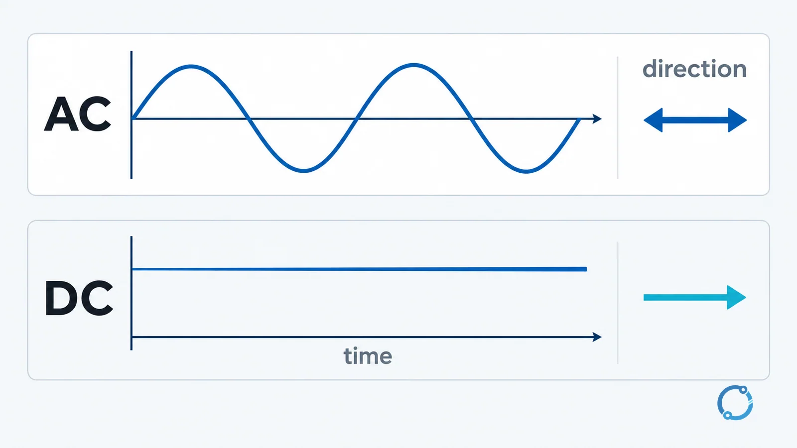
| Direction | Reverses direction periodically | Continues in one direction |
| Frequency | Has a defined repetition rate, such as 50 Hz or 60 Hz in common power systems | Has no power-frequency reversal; ripple or switching variation may still be present |
| Common sources | Alternators in generating stations, inverter outputs, utility supply | Batteries, photovoltaic modules, rectified power supplies, electronic converters |
| Transmission role | Can be transformed to higher or lower voltage for generation, delivery and use | Used in HVDC transmission where the project’s distance, cable or system conditions make it suitable |
| Storage | Not stored directly as AC in the usual grid sense; storage systems commonly convert between AC and DC | Batteries and many energy-storage elements hold or deliver DC |
| Typical uses | Bulk power generation and distribution, many industrial motors, building distribution | Electronics, controls, battery systems, photovoltaic arrays, electric-vehicle traction, data equipment |
The table gives orientation. The rest of the article explains the physical and system reasons behind it.
What AC current is
AC is current whose direction changes periodically. In a simple AC circuit, the current rises in one direction, falls back through zero, reverses, and then repeats. A graph of current against time therefore has a wave shape. In many power systems that shape is close to a sine wave, although real currents can contain harmonics and other distortion.
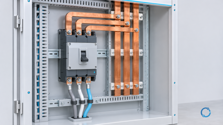
That changing direction is not a defect. It is what allows a transformer to transfer energy continuously. A transformer has no direct electrical connection between its primary and secondary windings in the ordinary two-winding model. Energy is transferred through a magnetic field in the core. Because the applied AC produces a changing magnetic flux, the secondary winding sees a changing flux and develops an induced voltage. The transformer principle explained here develops that mechanism in more detail.
AC also gives the grid a practical way to change voltage levels. Generation, transmission, distribution and final use often operate at different voltages. Transforming AC is a mature, efficient system function, not a claim that every voltage conversion is lossless. Losses, magnetizing current, heating and reactive-power behavior still matter.
The phrase “AC voltage” can describe more than one number because the waveform changes continuously. A utility supply described as 120 V or 230 V normally uses an RMS value. RMS stands for root mean square. For a sine wave, the RMS value is the peak value divided by the square root of two. Equivalently, the peak is the RMS value multiplied by approximately 1.414.
Worked example: RMS and peak
Assume a sinusoidal voltage has an RMS value of 120 V. Its ideal peak is:
V_peak = 120 V x sqrt(2)
V_peak = 120 V x 1.414
V_peak = 169.7 V
The peak is therefore approximately 170 V. The negative half-cycle reaches approximately -170 V relative to the chosen reference. This does not mean that the supply is “a 170 V system” in ordinary equipment descriptions. The RMS value is the conventional basis for many AC ratings because it represents the equivalent heating effect of the waveform.
The arithmetic assumes a sine wave. A distorted waveform can have a different relationship between RMS and peak, and a meter may use different measurement methods. That is one reason a single voltage number does not describe every waveform or power-quality condition. The basic voltage explanation separates potential difference from current, while the Ohm’s law guide shows how a resistive circuit relates voltage, current and resistance.
Frequency is the repetition rate
Frequency describes how many complete cycles occur in one second. Its unit is the hertz, where one hertz equals one cycle per second. If the current completes 60 cycles each second, its frequency is 60 Hz. A 50 Hz system completes 50 cycles in the same time.
Frequency is not the same as voltage. A system can maintain a nominal frequency while voltage changes, or maintain voltage while frequency changes, although the two are connected in a real power system. Frequency also affects transformers, motors, protection equipment and the timing of power-electronic controls.
The familiar 50 Hz and 60 Hz systems developed through different historical and standardization paths. This article does not need a country-by-country count to make the engineering point: equipment must be applied at the frequency and waveform for which it is designed, and a transformer or motor should not be assumed to behave identically when moved between systems.
What DC current is
DC current continues in one direction. A battery connected to a simple resistive load is the ordinary teaching example. The positive and negative terminals establish a polarity, electrons move through the external circuit in a consistent direction, and the voltage remains approximately constant while the battery’s state and load are stable.
Photovoltaic modules also produce DC. Light creates separated charge in the cell structure, and the module provides a DC output whose current and voltage vary with irradiance, temperature and the operating point set by the rest of the system. The solar-panel principle article follows that path from photons to a module’s DC terminals.
Electronic equipment usually works internally with DC. A power supply may rectify AC, smooth the result, and then regulate one or more DC rails for processors, sensors, radios or control circuits. Rectification is the conversion from AC to DC. It is not a statement that the original AC has disappeared; the converter has changed the form of the electrical energy and will have losses, heat and limits.
DC does not mean “no variation.” A battery voltage falls as it discharges, a PV output changes with sunlight, and a rectified supply can have ripple. A DC bus may also be switched rapidly by an inverter. The defining feature is the intended current direction, not a promise that every measured value is perfectly flat.
Why the grid uses AC
The strongest system-level reason is transformation. A transformer can step voltage up or down while transferring power through a magnetic field, and that magnetic field must change with time. An AC supply naturally provides that change. A steady DC current produces a steady magnetic flux in the simple transformer model and does not provide the same continuous transformer action.
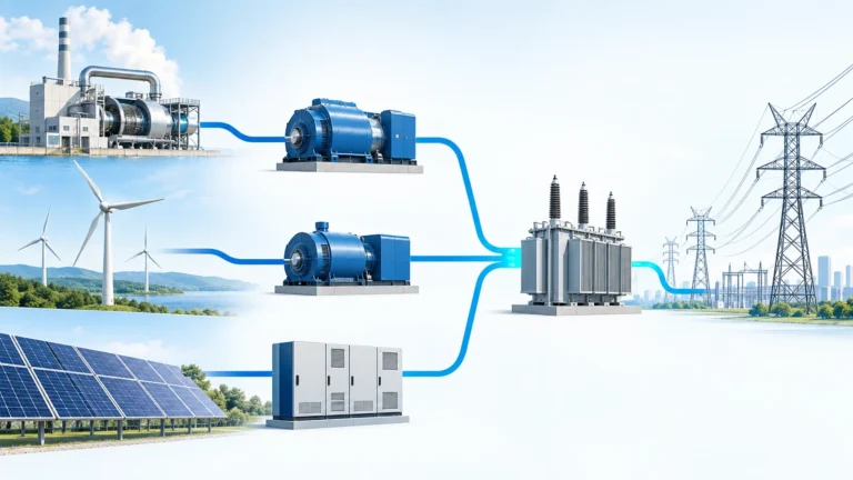
High-voltage transmission reduces the current required to deliver a given amount of power, and lower current reduces resistive losses in conductors for the same power and path. AC transformers make it practical to raise voltage at a generating or transmission point and lower it again for distribution and use. The U.S. Department of Energy’s electrical-science handbook describes this long-distance advantage as a major reason for generating and transmitting AC.
This does not mean that AC is the correct choice for every circuit. It means that a large synchronous grid, with many voltage levels and rotating machines, evolved around AC because transformation and generation fit together well. The choice is a system architecture, not a moral ranking.
The “war of currents” is often reduced to a story about one inventor defeating another. For an engineering reader, the durable lesson is narrower: AC and DC have different conversion, transmission and load-compatibility costs. Historic competition helped shape today’s grid, but it does not replace a present-day comparison of distance, power, cable, converter and availability requirements.
Where DC is preferred
DC is not a niche exception. It is the normal internal form for many loads:
- Batteries store and deliver DC, so a battery energy-storage system needs a converter when it connects to an AC grid.
- Photovoltaic modules generate DC, and an inverter converts that output for an AC grid or an AC building distribution system.
- Computers, communications equipment, sensors and control electronics generally use DC rails internally.
- Electric vehicles use DC batteries and power electronics to control traction machines.
- High-voltage direct current (HVDC) transmission can be suitable for very long overhead routes and some submarine-cable projects because it changes the system-level tradeoffs.
These examples do not prove that a house or factory should replace every AC circuit with DC. They show that conversion is a normal part of electrical systems. A designer chooses the form that fits the source, load, distance, protection, transformation and interoperability requirements.
The source-to-load chain also explains why electricity generation and delivery cannot be described by one waveform alone. The guide to how electricity is generated places rotating generators, photovoltaic sources and other production methods in the same system context.
How the two compare in practice
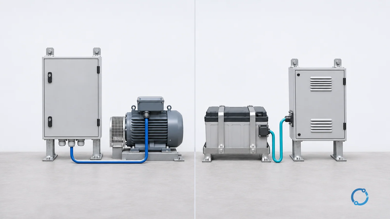
For a battery-powered device, DC is usually the direct interface: the battery, the load and the internal electronics can share a DC bus. For a building supplied by a utility, AC is usually the available distribution form. A power supply or inverter is then needed at the boundary.
For a motor, the answer depends on the motor and control scheme. AC induction motors are common in industrial systems, while DC motors and electronically commutated machines appear in other applications. A drive can change voltage and frequency for an AC motor, which is a form of power conversion rather than a change in the fundamental definition of AC.
For transmission, AC remains the dominant architecture because of the existing grid, transformers and rotating generation. HVDC is selected where its converter stations, cable capacitance, distance and interconnection requirements provide a better system solution. The comparison is therefore project-specific, not a universal winner-takes-all decision.
Common misconceptions
“AC is always more dangerous than DC”
Electrical hazard depends on current magnitude, path through the body, duration, voltage, contact conditions and the available energy, not on the AC or DC label alone. A low-voltage DC source can still be hazardous in some conditions, and an AC supply can be designed and guarded safely. Qualified persons should follow the applicable isolation, verification and work rules.
“A 120 V AC supply has a constant 120 V”
The number is commonly an RMS value for a changing waveform. For a sine wave with 120 V RMS, the peak is approximately 170 V. The instantaneous voltage passes through zero and reverses every cycle. Equipment ratings, insulation and measurement methods must be read in that context.
“DC means a perfectly steady battery voltage”
The direction may be constant while the magnitude changes. Batteries discharge, photovoltaic output varies and rectified supplies can contain ripple. A DC measurement describes the actual voltage and ripple conditions, not an ideal mathematical line.
FAQ
What is the main difference between AC and DC current?
AC periodically reverses direction, while DC continues in one direction. The difference affects how the current can be transformed, how sources and loads connect, and which protection and conversion equipment is appropriate.
Why does the grid use AC instead of DC?
AC can be transformed to different voltages through equipment that uses a changing magnetic field. That makes it practical to raise voltage for transmission and lower it for distribution and use. The grid also developed around AC generation and transformers, although HVDC is used where its system economics are suitable.
Why does a 120 V AC supply have a peak of about 170 V?
For a sinusoidal waveform, the peak equals the RMS value multiplied by the square root of two. 120 V x 1.414 = 169.7 V, which is approximately 170 V. The RMS value is the conventional value used for many AC descriptions and ratings.
Is DC used only in batteries?
No. Batteries are a common DC source, but photovoltaic modules, electronic power supplies, electric-vehicle systems and many control circuits also use DC. An inverter or converter is used when the DC system must connect to an AC source or load.
Can a transformer work on steady DC?
A transformer transfers energy through a changing magnetic flux. A steady DC current does not provide the same continuous changing flux in the ordinary transformer model. A transformer should be applied only within the supply and equipment conditions for which it is designed.