
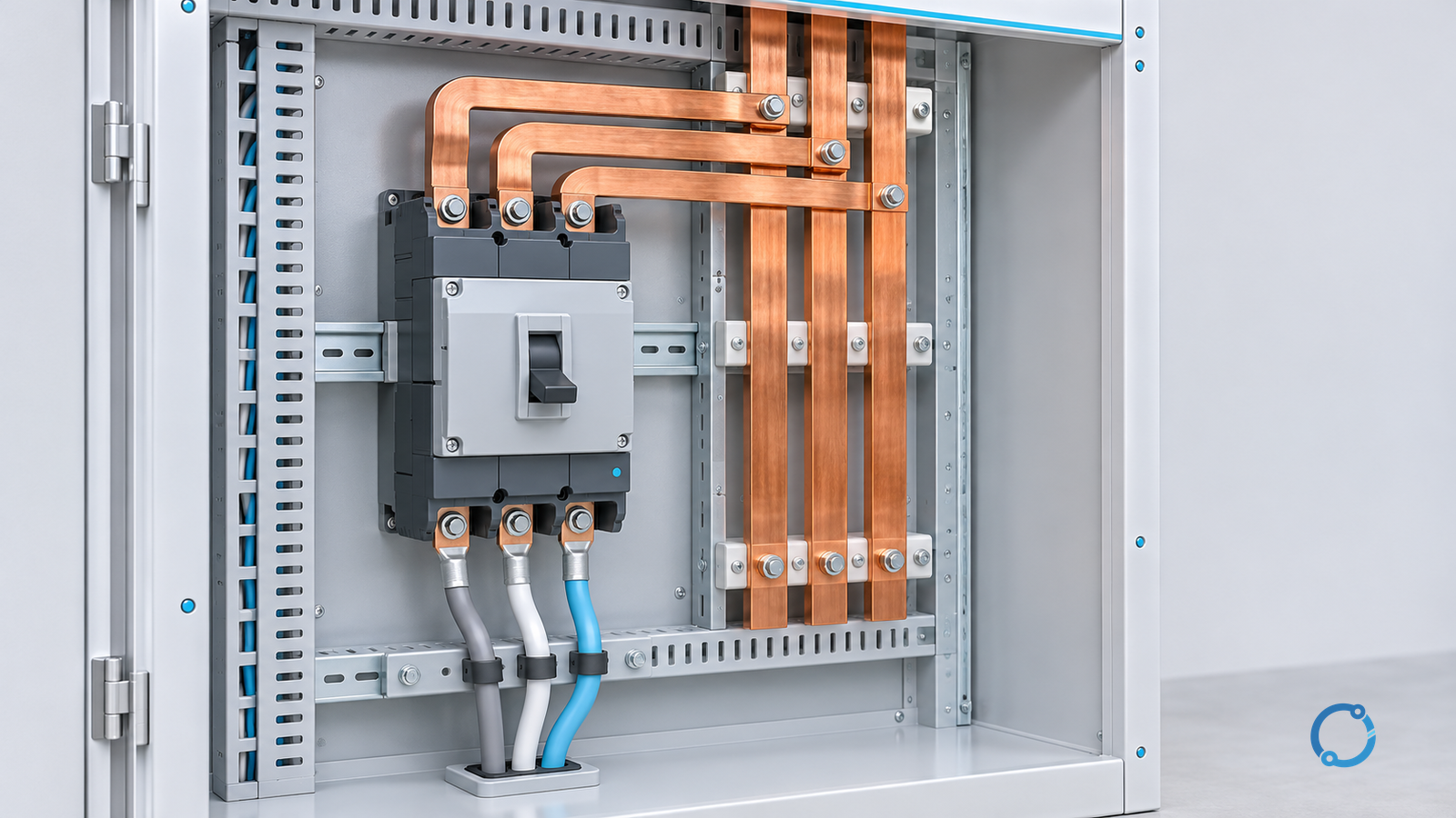
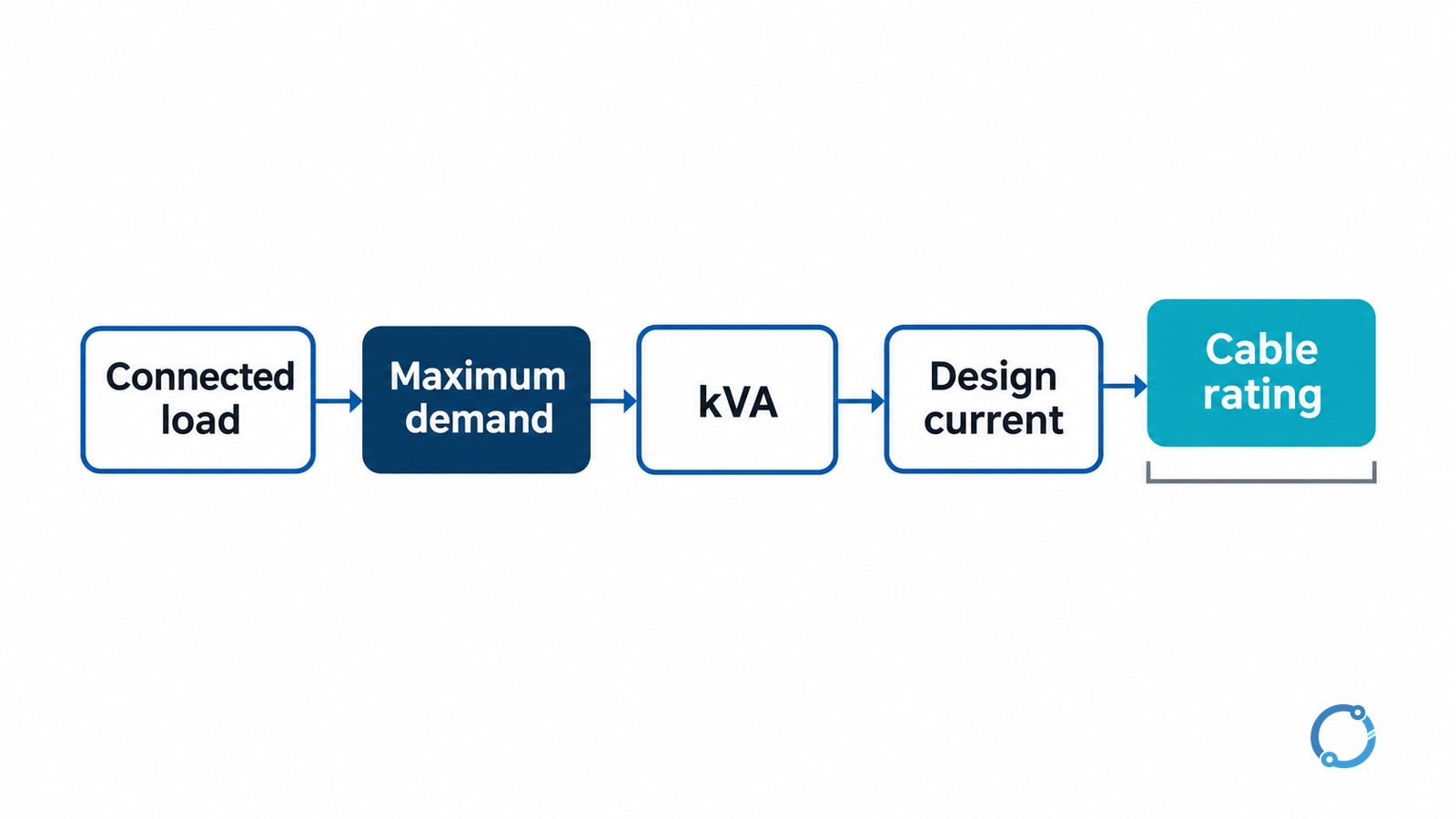
Maximum demand is not the sum of every connected load. It is the greatest demand expected over a defined assessment period after the applicable demand methodology has been applied. To move from connected load to a cable current check, use a five-stage chain:
connected load -> maximum demand -> kVA -> design current -> corrected cable current rating
Each stage has assumptions. The connected load is an inventory. The maximum demand depends on diversity, operating schedule, duty, and the rules or study method chosen for the project. The kVA conversion depends on power factor. The current calculation depends on whether the system is balanced three-phase. The cable check depends on installation method, ambient temperature, grouping, conductor material, insulation, voltage drop, and protection.
This article provides the arithmetic and a worked example. It does not supply a universal diversity factor, cable size, or code rule. Those values must come from the project basis and the locally adopted electrical code.
In the United States, NFPA 70 is the National Electrical Code. The official NFPA 70 overview identifies the code framework, but the applicable edition and local amendments still control the design. Other jurisdictions use different installation rules and terminology.
Stage 1: assemble the connected load
Start with a load schedule rather than a single total. For each load or group, record:
- equipment name and location;
- rated input power or demand;
- voltage, phase, and frequency;
- power factor or kVA rating;
- duty cycle and expected operating hours;
- whether the load is continuous, intermittent, standby, or transient; and
- the source or calculation basis for the value.
Connected load is the sum of the connected equipment ratings, but those ratings may not be directly comparable. A motor’s mechanical output is not its electrical input. A transformer may be rated in kVA rather than kW. A drive may have an input current that differs from its output current. A nameplate may describe a worst-case condition that is not the normal operating condition. Normalize the data before adding it.
For a first-pass estimate, a designer may group similar loads and apply a documented demand factor. The factor is not a universal constant. It depends on the load type, the facility’s operating pattern, the assessment interval, and the rules governing the design. The OHELE transformer kVA selection guide discusses load duty in a related equipment context.
Stage 2: convert connected load to maximum demand
A simple planning expression is:
Maximum demand = connected load x demand factor
The expression is only as good as the factor. A data center, a workshop, a hotel, and a water-treatment plant do not share one diversity assumption. The designer should be able to explain why the selected factors represent the expected maximum, not merely why they make the total smaller.
An illustrative calculation can show the arithmetic without implying an industry rule. Suppose four groups have connected demands of 45 kW, 30 kW, 22 kW, and 18 kW. The sum is 115 kW. If the project’s documented factors are 0.80, 0.70, 0.60, and 0.50, the diversified demand is:
0.80 x 45 = 36.0 kW
0.70 x 30 = 21.0 kW
0.60 x 22 = 13.2 kW
0.50 x 18 = 9.0 kW
Maximum demand = 36.0 + 21.0 + 13.2 + 9.0 = 79.2 kW
The factors and load values in this example are illustrative. A real schedule should show the source of every factor and should consider whether the maximum demands of the groups can occur simultaneously. A sum of individual maxima can overstate the coincident demand; a single average factor can understate a short but important peak.
Stage 3: convert kW demand to kVA
For a load with a known active-power demand and an assumed or measured power factor:
kVA = kW / power factor
Using the illustrative 79.2 kW demand and a power factor of 0.90:
kVA = 79.2 / 0.90 = 88.0 kVA
The power factor must match the load and the point of calculation. A facility with several motors, drives, transformers, and standby sources may not have one constant power factor. If the calculation is being used to select a transformer, generator, or cable, use the design power factor stated in the project basis rather than a generic value from an unrelated site.
Reactive-power compensation can change the current for the same active-power demand, but it does not erase the need to calculate the load at the actual operating condition. The purpose of the conversion is to preserve the difference between kW and kVA. Treating them as interchangeable can understate current and equipment loading.
Stage 4: calculate balanced three-phase current
For a balanced three-phase system, the line current can be calculated from apparent power:
I = kVA x 1,000 / (sqrt(3) x line voltage)
With 88.0 kVA at a 400 V line voltage:
I = 88.0 x 1,000 / (1.732 x 400) = 127 A
The same result can be obtained from kW, voltage, and power factor using the three-phase input-power formula. The kVA route is often easier to audit because it keeps apparent power separate from active power.
The formula assumes balanced phase currents and an approximately sinusoidal system. It is not a substitute for a phase-by-phase load flow when the load is unbalanced, when significant harmonics are present, or when the design includes a mixture of single-phase and three-phase branches. The result is a design current estimate, not a measurement of an existing feeder.
Stage 5: compare with cable current rating
A cable’s tabulated current rating is a starting value. The installed current-carrying capacity may be lower after correction for:
- ambient or soil temperature;
- grouping with other loaded cables;
- installation method and enclosure;
- thermal resistivity where applicable;
- conductor material and insulation temperature rating;
- harmonic content; and
- the project’s rules for continuous or cyclic loading.
If the applicable correction factors multiply to 0.80, a candidate cable with a tabulated rating of 160 A has an adjusted capacity of:
160 x 0.80 = 128 A
That is only slightly above the illustrative 127 A design current. The margin may be inadequate once measurement uncertainty, future load, termination limits, voltage drop, and protection are considered. A different installation method or conductor size may be required.
The OHELE cable-sizing guide covers the interaction between conductor ampacity and protective-device selection. The circuit-breaker sizing guide covers the protection side. A cable check that stops at “adjusted ampacity is greater than design current” is incomplete.
The checks that follow the current comparison
The maximum-demand calculation gives the designer a design current. It does not finish the feeder design. The next checks include:
- Protective-device compatibility. The overcurrent device must protect the conductor and the equipment within the applicable rules.
- Voltage drop. The selected conductor must deliver acceptable voltage at the load under starting, steady-state, and transient conditions.
- Short-circuit withstand. The cable and its terminations must withstand the available fault energy for the clearing time.
- Termination temperature and size. The conductor must be compatible with the equipment terminals and the installation method.
- Neutral and protective conductors. Their sizing and routing are separate design requirements.
- Future load and spare capacity. The project basis should state whether spare capacity is required.
These checks are connected, but they are not interchangeable. A cable selected for ampacity may fail voltage drop. A cable selected for voltage drop may be larger than the minimum thermal size. A protective device selected for the load may not coordinate with upstream protection. The design must satisfy all applicable constraints.
A worked summary
The illustrative chain is:
| Stage | Result | Main assumption |
|---|---|---|
| Connected load | 115 kW | Sum of the four normalized group demands |
| Maximum demand | 79.2 kW | Project-specific demand factors |
| Apparent power | 88.0 kVA | Design power factor of 0.90 |
| Balanced three-phase current at 400 V | 127 A | Balanced sinusoidal system |
| Candidate cable adjusted capacity | 128 A | Tabulated 160 A times a 0.80 combined factor |
The final row is not a cable selection. It shows how close an apparently adequate tabulated rating can become after correction. The next step is to obtain the actual cable data and installation factors, check voltage drop and fault withstand, and coordinate the protective device.
Common mistakes
Adding nameplate kW without normalizing input and output. A motor’s shaft rating is not its electrical input. A transformer’s kVA rating is not a kW load. Normalize the units and the boundary before summing.
Using a generic diversity factor. A factor copied from another project can hide a peak or overstate spare capacity. Document the basis and check coincident operation.
Ignoring power factor. A kW total cannot be converted to current without an apparent-power basis. State the design power factor and its source.
Treating tabulated ampacity as installed ampacity. Installation method, ambient, grouping, and conductor temperature rating change the usable current.
Stopping before voltage drop and protection. Thermal ampacity is one constraint. The feeder must also satisfy voltage, fault, termination, and coordination requirements.
The OHELE standby-generator sizing guide shows a related load-step perspective. A generator may have to accept motor starting or block loads that a diversified steady-state maximum-demand calculation does not reveal. That is another reason to keep the purpose of the calculation explicit.
The bottom line
Maximum demand is the result of a documented load study, not a synonym for connected load. Convert the selected demand to kVA with the correct power factor, calculate balanced three-phase current with the voltage and assumptions stated, then compare that current with a cable rating corrected for the real installation.
Use the result as the entry point to protection, voltage drop, fault withstand, termination, and code review. The arithmetic is simple; the engineering value comes from making every assumption visible and refusing to let one number stand in for the whole design.