
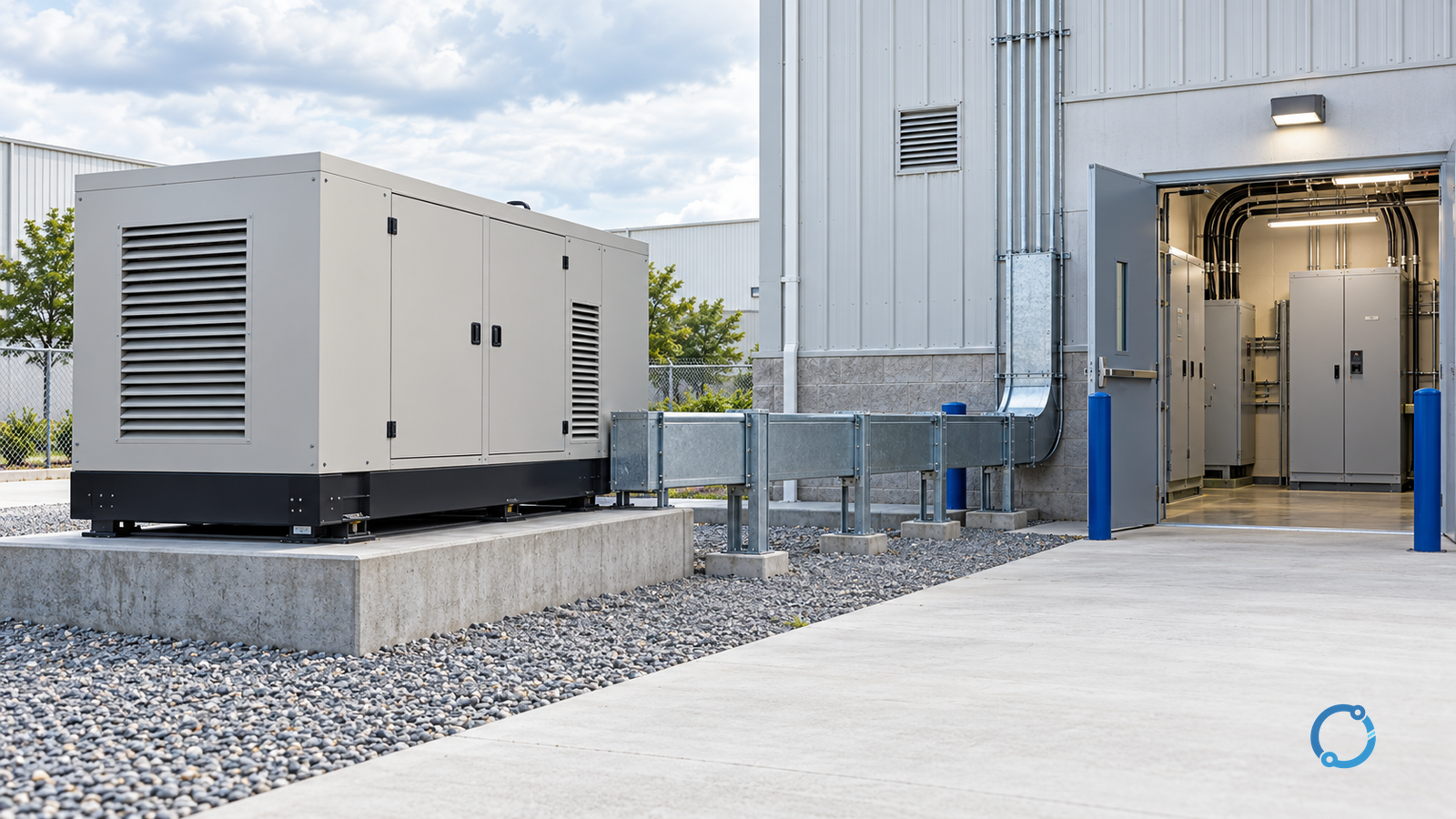
Standby generator sizing starts with an operating sequence, not an arithmetic sum of connected loads. The generating set must carry the steady load that is actually transferred, accept the largest credible load step and keep voltage and frequency within the limits required by the supplied equipment. It must also coordinate with the transfer arrangement, generator breaker, protection and any source that can operate in parallel or during a transition.
A schedule that simply adds every nameplate kilowatt creates two errors. It may overstate the steady load by ignoring diversity and demand, while understating the difficult condition: a motor, transformer, rectifier or group of loads starting in a particular order with limited source capability. Conversely, selecting a generator only for a calculated kW value can leave the voltage or frequency disturbance unacceptable even when the thermal rating appears sufficient.
This guide describes a transparent sizing workflow. It does not provide a universal capacity margin, voltage-dip limit, frequency-recovery limit or starting method. Those values are project inputs derived from sensitive-load requirements, the generating-set performance evidence, the transfer topology and the applicable standards. ISO 8528-1:2018 covers application, rating and performance concepts for generating sets; ISO 8528-5:2025 addresses generating-set design and performance in its scope; and ISO 8528-3:2020 addresses generator characteristics with excitation-control systems. None of those standard pages supplies a project’s exact acceptance limit.
Generator testing and live transfer work must be carried out by qualified persons under the site’s approved switching, isolation, protection and risk-control procedures. In U.S. general industry, OSHA 29 CFR 1910.333 provides a work-practice boundary for the electrical work involved.
The sizing answer is a sequence of operating states
Define these states before comparing generator products:
- Normal supply with the generator disconnected.
- Generator start and stabilisation before transfer.
- Transfer of the first load group.
- Each subsequent load step.
- Steady standby operation after all permitted loads are connected.
- Loss of one source or abnormal operating condition.
- Return transfer and generator cooldown.
For each state, record which loads are connected, which are running, which are starting and which are intentionally blocked by the transfer control. A generator may be comfortable with the final steady load yet fail the sequence because two large motors start at the same time.
Build a load schedule with real operating data
Create one row per load group or significant load:
| Field | Purpose |
|---|---|
| Load identifier and served equipment | Links the electrical load to the process consequence |
| Rated voltage, phase and frequency | Confirms compatibility with the generator source |
| Rated kW and kVA | Establishes apparent and real power demand |
| Power factor or converter data | Separates real and reactive or distorted demand |
| Running demand and duty | Avoids summing connected nameplates |
| Starting method and starting current | Defines the transient step |
| Starting duration and load order | Shows whether disturbances overlap |
| Sensitive-load limit | States what the protected equipment can tolerate |
| Priority and transfer group | Connects electrical sequence to operational priority |
| Harmonic or DC characteristics | Captures source and filtering requirements |
| Environmental or process constraints | Records ambient, altitude, fuel and ventilation dependencies |
Use measured running power where available. For a new installation, use the driven-equipment design data and the design team’s demand assumptions. Do not insert a generic percentage merely to make the table look complete. The assumption must be visible, named and testable.
The sum of all connected kW is a useful inventory check, not a final generator rating. Record both connected load and the scheduled running load under each scenario. A fire pump, life-safety load, process chiller or IT load may have a mandatory priority or run condition that changes the actual demand.
Separate kW, kVA and transient capability
Real power and apparent power describe different demands. Generator capacity cannot be selected from kW alone when the load has reactive or distorting current. The project also needs the generator’s continuous rating basis and its verified capability at the relevant conditions.
ISO 8528 rating terms are not interchangeable. The class or rating declared for standby service must match the intended duty, load profile and site conditions. The manufacturer’s performance data should identify the complete generating set, not just an engine or alternator in isolation.
Check what the offered performance evidence includes:
- alternator capability at the design power factor;
- engine governor response under the defined load step;
- voltage recovery after motor starting or a major load change;
- frequency recovery and stability on the connected load;
- limits at elevated ambient, altitude and enclosure conditions;
- behaviour with harmonic-rich loads;
- fuel, cooling and ventilation requirements;
- excitation and voltage-regulation settings;
- ability to operate with the transfer and protective equipment being supplied.
A nameplate kVA can be consistent with several different transient responses. The term “generator capacity” hides that distinction if the offer lacks load-step and disturbance data.
Define the motor-starting disturbance limit
Motor starting is a system event. The generator, cables, transformer, transfer switch, contactors, motor starter, driven inertia and other connected loads all participate. The acceptance limit belongs at the terminals of the equipment that must keep operating.
For every significant motor, record:
- motor rating and starting method;
- locked-rotor or starting current at the relevant voltage;
- starting torque and driven-load torque;
- acceleration time;
- direction and sequencing constraints;
- acceptable voltage dip at generator terminals;
- acceptable voltage at sensitive-load terminals;
- acceptable frequency dip and recovery;
- protection and starting limits;
- reset or restart behaviour after a failed start.
The generator supplier should be asked for evidence against this schedule. If the generator cannot satisfy the largest step alone, the review may consider starting method, staged starting, reduced-voltage starting, variable-speed drive compatibility, additional source support or smaller incremental steps. The solution must remain electrically and mechanically valid for the driven process.
Do not assume that a soft starter, drive or reduced-voltage starter solves every source problem. These methods change the current and torque profile, introduce harmonics or control interactions, and may not be suitable for all motors. Do not assume that a single successful start proves capability under hot engine, low ambient, degraded fuel or additional connected-load conditions.
Treat load switching as a sequence, not a total
Suppose the final connected load is within the generator’s steady rating. Two motors still cannot start together if their combined transient step is beyond the generator’s capability or causes an unacceptable bus voltage dip. A transfer scheme also may impose its own step when it connects a group of running loads.
Build a step table:
| Step | Loads connected before step | Load starting at step | Additional kVA | Duration | Voltage-sensitive loads at risk | Evidence required |
|---|---|---|---|---|---|---|
| G-1 | Controls only | First motor | Defined by start study | Starting interval | Controller and instrumentation | Supplier step data |
| G-2 | First motor running | Next load group | Defined by transfer schedule | Transfer transition | All connected loads | Load-step test data |
| G-3 | Base process running | Largest motor | Defined by motor data | Acceleration time | Process controllers | Site acceptance record |
The numbers in a project table must come from the actual study. A table with blank evidence is a warning sign, not a complete sizing calculation.
Check the source-to-load topology
The generator is only one part of the standby source. Review the transfer arrangement and every path used during startup, transfer, operation and return:
- automatic transfer switch or manual changeover;
- transfer switching poles and neutral configuration;
- generator circuit breaker and protection;
- busbar and cable current ratings;
- source impedance and fault levels;
- earthing and bonding arrangement;
- standby and normal source interlocks;
- isolation of non-essential loads;
- closed-transition or momentary parallel operation, if proposed;
- reverse-power or loss-of-mains protection;
- generator neutral-earth relationship;
- control supply and battery autonomy;
- fire, life-safety and emergency-system priorities.
The generator breaker must be compatible with the fault contribution and protection philosophy of the complete system. A generator with enough kW for the load can still be part of an unsafe or non-selective protection arrangement. For related guidance, compare the OHELE articles on generator circuit-breaker breaking capacity, generator paralleling and three-pole versus four-pole transfer switches.
Include environmental and fuel conditions
Engine and alternator performance depends on the actual environment. Ambient temperature, altitude, enclosure, air intake and exhaust restrictions affect combustion and cooling. The standby source also needs a reliable starting means, a defined fuel supply and a cooling arrangement that works under the expected site conditions.
Do not add a generic derating percentage without the manufacturer’s basis. Record the correction from the offered product data and the assumed site conditions. Verify that the generator enclosure has adequate airflow and that exhaust cannot recirculate into the intake. Confirm that fuel storage and delivery meet the applicable fire, environmental and operational requirements.
Loads that change over the life of the installation matter too: a future chiller, charger or motor may make an initially comfortable generator marginal. Define expansion assumptions and protect the schedule from undocumented additions.
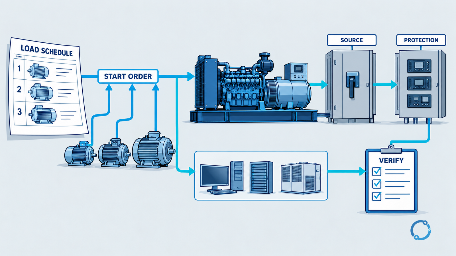
A six-gate sizing workflow
Gate 1: establish the standby operating objective
Define which loads must run, for how long and with what consequence if they stop. Separate life-safety, critical process, non-essential and future loads. Confirm whether the set is intended for standby, prime or another duty and whether the standard invoked by the project applies.
Gate 2: build the demand and starting schedule
Record actual running demand, starting current, power factor, driven-load torque, start duration and operating state. Include every load group connected after transfer, not only the largest motor.
Gate 3: set the disturbance envelope
Identify the voltage and frequency limits at the sensitive-load terminals, including the duration and recovery basis. Obtain these from the equipment requirements, process owner and applicable project standard. Keep them separate from the generator supplier’s internal performance values.
Gate 4: obtain complete generating-set evidence
Request engine-governor and alternator-excitation performance for the complete offered set at the project conditions. Ask for the largest credible load step, sequential steps and operation with the specified nonlinear or unbalanced load. A catalogue kVA alone is insufficient.
Gate 5: verify the system interfaces
Check transfer topology, neutral and earthing, breaker fault duty, conductor ratings, protection, source interlocks, control supplies, ventilation and fuel. Ensure the generator cannot be connected in an invalid parallel or backfeed state.
Gate 6: prove the result through a controlled test plan
Define the factory or supplier evidence and the site acceptance test. Include startup from cold and warm states, sequential loading, largest allowable step, transfer and return, protection operation and documented disturbance measurements. Test only under the approved switching and safety procedure.
What to include in a supplier request
A useful request does not ask for “a generator suitable for the building.” It supplies a schedule and asks for evidence against it:
- project location, ambient and altitude;
- load schedule by operating state;
- starting method and current/torque data;
- voltage and frequency acceptance criteria at defined terminals;
- source and transfer topology;
- earthing arrangement;
- expected nonlinear load spectrum or device data;
- fuel and enclosure requirements;
- protection and communication requirements;
- required documentation and test witnesses.
Ask the supplier to identify the exact rating basis and any assumption that changes the offered capability. State that a proposed derating, external starting aid or load-management change must be visible rather than buried in a model number.
Reviewing a seemingly oversized or undersized option
An apparently oversized generator can still have poor transient response if the excitation, governor or load-step capability is inadequate. It can also operate at a low load, with fuel and emissions consequences that must be considered. An apparently undersized generator may be acceptable if the process inherently stages loads, uses reduced-current starting or has a verified load-management scheme.
The engineering question is therefore conditional:
- choose a larger generating set when the verified sequence still exceeds the smaller set’s disturbance or thermal capability;
- choose a smaller set with staged starting when the controls and process can enforce the sequence;
- choose a different starter or drive only after motor, driven load, harmonics and protection are assessed;
- reject an offer when its rating basis or load-step evidence does not match the project.
No universal winner exists without those inputs.
Common sizing errors
Adding connected nameplates without demand. Installed load and operating load are different quantities.
Checking only the largest motor. Multiple simultaneous starts, transfer steps and sensitive loads can be worse than one isolated motor.
Using a maker’s maximum kVA without the performance basis. The offer must match ambient, altitude, power factor, control scheme and duty.
Ignoring voltage at the sensitive load. The generator terminals may remain acceptable while a remote controller or contactor sees a disturbance.
Using generic margins. A margin can hide uncertainty but cannot replace a load schedule or disturbance study.
Ignoring fault duty and protection. Starting and carrying load do not establish safe interruption or selective coordination.
Ignoring the return transfer. Load rejection, cooldown and restoration can create another sequence of switching and thermal states.
Final verification record
The final sizing record should contain the load schedule, operating-state diagram, starting sequence, accepted disturbance limits, offered generating-set performance, environmental corrections, transfer and protection review, and test evidence. Each revision should state what changed: a load, a start method, a limit, a source topology or a product-rating assumption.
If a value cannot be substantiated, mark it as an open item and keep the generator selection conditional. A reviewable standby system is one whose steady capability, transient response and source compatibility all point to the same load sequence. The useful related OHELE guides are comparing motor starting methods, closed-transition transfer-switch coordination and generator paralleling checks.
Sources
- ISO 8528-1:2018 — Generating sets: application, ratings and performance
- ISO 8528-5:2025 — Generating sets: design and performance
- ISO 8528-3:2020 — AC generators for generating sets
- IEC 60034-1:2026 — Rotating electrical machines: rating and performance
- NFPA 110 — Emergency and standby power systems
- OSHA 29 CFR 1910.333 — Selection and use of work practices