
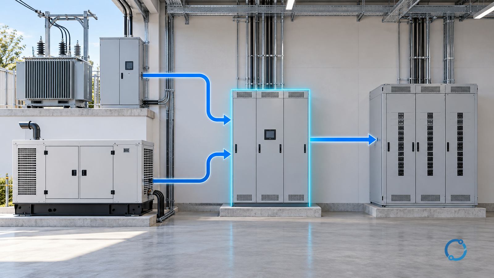
A closed-transition transfer switch briefly parallels the source and load during a changeover, reducing the interruption that an open transition creates. It is not simply a faster transfer. For the parallel interval, the facility temporarily has a new electrical source configuration with new fault contributions, voltage and frequency interactions, and protection duties. The scheme is defensible only when every one of those conditions is engineered, rated and tested.
This guide is a selection and commissioning review for low-voltage facility power systems that transfer between a utility supply and a generator or another source. It does not provide utility interconnection approval, generator control settings, switching instructions or permission to work energized.
Define the exact topology before choosing a switch
Record every source and its role:
- utility service and transformer;
- generator or generators;
- alternate feeder or another transformer;
- normal, standby and maintenance states;
- neutral and grounding arrangement;
- transfer switch position and bypass/isolation arrangement;
- protection devices on each source and the common load;
- any essential or nonessential downstream distribution.
The same transfer-switch label can be used for an open transition, a closed transition, a soft-load transfer or a bypass-isolation arrangement. Confirm the switching sequence and the number of poles from the approved single-line, not from the product name.
The transfer switch assembly should be treated as a system boundary. The IEC 61439-1:2020 catalog and the IEC 61439-2:2020 catalog identify the general and power-assembly scopes; an individual breaker or contactor that is suitable on its own does not establish the complete transfer assembly.
Understand what “parallel” means in the sequence
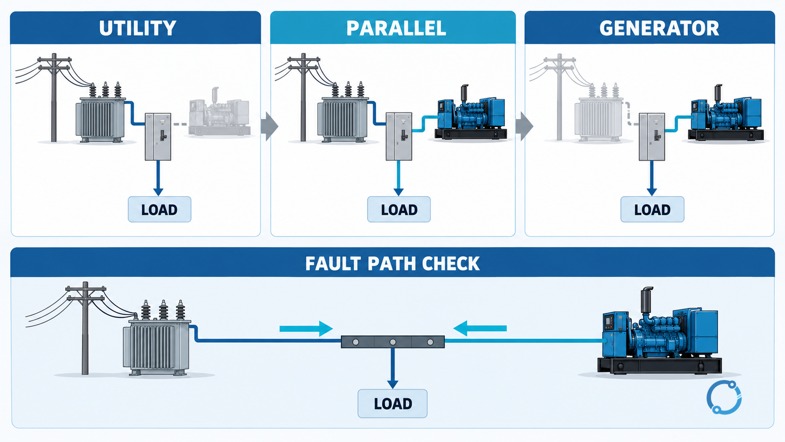
A conceptual closed transition has four stages:
- Source available: both source voltages, frequency and phase conditions are monitored.
- Parallel interval: the incoming source is synchronized and connected while the outgoing source remains closed.
- Load transfer: the load is transferred or the outgoing source is unloaded.
- Separation: the outgoing source is disconnected and the system returns to a single-source state.
The parallel interval is intentionally short, but it is electrically real. It can create a new fault-current path, altered voltage regulation, generator reverse-power or motoring risk, and a different protection response. The switch must not be treated as a passive changeover contact.
Check source compatibility before fault coordination
Closed transition requires the two sources to be compatible enough to connect:
| Check | Why the parallel state changes the question |
|---|---|
| Voltage magnitude and tap | A large difference drives reactive or circulating current |
| Frequency and speed control | A generator that cannot hold frequency creates power oscillation |
| Phase angle and phase sequence | Closing without the required synchronism can produce severe current |
| Voltage waveform and harmonics | Distorted sources may interact with controls and loads |
| Neutral and grounding | Parallel neutrals and earth paths can change fault and protective-conductor behavior |
| Source capacity | A small generator may be overloaded by the transfer or load |
| Generator protection | Reverse power, loss-of-mains and overcurrent functions must remain valid |
Generator sizing for large motor starting is a separate transient-recovery study. A generator that can accept a block load may still be unsuitable for parallel operation if its controls cannot maintain compatible voltage and frequency.
Do not infer source compatibility from a nominal voltage match. A 400 V utility and a 400 V generator are not electrically interchangeable if the phase sequence, winding arrangement, grounding or control response differs.
Recalculate fault duty in the parallel state
The parallel state can combine source contributions. A fault on the common bus may receive current from the utility transformer and the generator at the same time. Downstream breakers and the transfer assembly must be evaluated for the prospective current and duration in that configuration, not just for the normal single-source state.
For a balanced three-phase short-circuit current estimate at a defined point, the relationship is:
I_sym = S_sc / (sqrt(3) x VLL)
where S_sc is the specified symmetrical short-circuit apparent power at that voltage and I_sym is the corresponding line current. This is a conversion for a study result, not a replacement for the source and network model. Transformer impedance, generator subtransient behavior, cable impedance, motor contribution and the actual fault point determine the result.
Check:
- maximum and minimum fault currents in every transfer state;
- breaker interrupting, making and short-time withstand ratings;
- fuse or relay clearing behavior at the parallel current;
- equipment and busbar short-circuit withstand;
- protective-device coordination during and after transfer;
- the effect of intentional delay on arc-flash incident energy.
The existing LV breaker selectivity guide explains why a generic upstream/downstream breaker pair is not enough. Overcurrent relay coordination shows how timing and current ranges must be tested together. A closed-transition scheme needs both kinds of evidence in the parallel mode.
Prevent an accidental or extended parallel condition
The normal sequence may be brief, but abnormal conditions can extend it:
- synchronizing check failure;
- a stuck contactor or breaker;
- control-power loss;
- failure to unload the outgoing source;
- reverse-power protection not operating;
- a maintenance bypass left in the wrong state;
- a sensor or controller giving an incorrect source-ready signal.
Define the intended failure response and how it is detected. A closed-transition switch should have an engineered means to prevent closure when the sources are outside the permitted window and to separate them if the sequence does not complete. The exact logic, timing and safe state depend on the switchgear and plant design; they are not universal settings.
Do not use the transfer switch to parallel sources for normal peak shaving or continuous generator operation unless that different operating mode has been specifically engineered and approved. The product’s closed-transition function does not create a general paralleling capability.
Treat neutral and grounding as a system study
A transfer switch changes which source neutral and grounding path is connected. The design must show:
- whether each source is solidly grounded, impedance-grounded or otherwise arranged;
- whether the neutral is switched or solidly connected;
- how the equipment grounding conductor and bonding path remain effective;
- how fault current returns to its source;
- whether a parallel neutral path can carry current during the transition;
- how protective devices detect a fault in each state.
The neutral earthing system selection guide covers the fundamental choice. It does not decide the transfer-switch pole configuration. A transferred neutral can create unintended parallel paths if the source arrangements were not designed for it, and an unswitched neutral can create a different issue in a separately derived system. Resolve the topology with the responsible electrical engineer and the locally adopted installation rules.
Build the commissioning evidence register
Testing belongs to qualified personnel under an approved isolation, switching and restoration plan. Closed-transition testing can create a parallel source condition, so the test setup and authority must be explicit.
| Evidence item | What it should establish |
|---|---|
| Approved single-line and control sequence | The intended states and source boundaries are unambiguous |
| Source data and compatibility calculation | Voltage, frequency, phase angle, capacity and controls are within the design basis |
| Fault study for every state | Parallel and single-source duties, including minimum and maximum cases |
| Protection settings and coordination | Each source and load device has a defined response |
| Assembly ratings and certification evidence | The complete switchgear, not just one device, is suitable |
| Neutral/grounding review | Fault and protective paths are valid in each mode |
| Functional test procedure | The sequence, interlocks, failure response and restoration are defined |
| As-left record | Test switches, bypasses, settings and control modes are restored |
Test sensors, relays and controllers without assuming that a green status indication proves the complete clearing chain. Record the actual source voltages, frequency, phase relationship and transfer sequence during permitted tests. A simulated signal can verify logic but not the physical source behavior.
Apply a release gate
Do not release a closed-transition scheme merely because the switch operated once. Require:
- a verified topology and switching sequence;
- a fault study that includes the parallel state;
- source controls that maintain the required compatibility;
- complete assembly and protective-device evidence;
- a neutral/grounding review for every mode;
- a test and restoration record with no unresolved bypass.
If any gate is missing, the correct state is hold: use an open transition or another approved arrangement until the evidence is complete. A closed transition is a system capability, not a checkbox on a transfer-switch datasheet.
For the broader safety consequence of clearing-time changes, see Arc-Flash Risk Reduction: Maintenance, Mitigation and Containment. For source-side switching equipment, the medium-voltage switchgear switching-device guide distinguishes breakers, switches, disconnectors and earthing duties.