
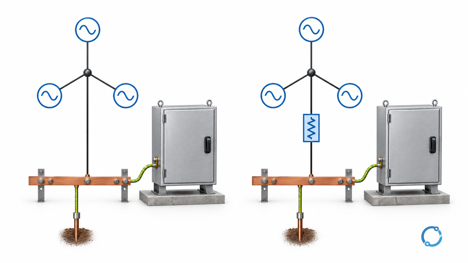
Choose a neutral earthing system by deciding how the installation must behave during a phase-to-earth fault, then verifying that the source, connected loads, insulation and protection can support that behavior. A desired fault-current number is an input to the study—not the whole selection.
For an industrial AC system, the choice may involve a solid connection, a neutral resistor, or another engineered arrangement. High-resistance grounding can support a controlled first-fault response in suitable systems, but it is not permission to ignore a ground fault or remove protective bonding.
This guide concerns the source-neutral connection in industrial power systems. It does not design a building’s protective-earthing arrangement, select domestic wiring, or calculate an earth-electrode grid. “Earthing” and “grounding” refer to the same source-neutral topic here.
Separate the neutral connection from equipment bonding
The source-neutral connection affects earth-fault behavior. Protective bonding connects exposed conductive equipment parts into the intended protective network. Limiting current through a neutral resistor does not remove the need for those equipment connections.
IEEE 3003.1-2019 is an active recommended practice for grounding industrial and commercial power systems. Its official catalog establishes the document’s scope; the locally applicable rules and full design guidance still need review.
Before selecting an arrangement, record the source winding and available neutral, system voltage and frequency, line-to-neutral loads, operating sources, cable extent, insulation environment, fault-detection method and intended first-fault response.
A current transformer (CT) supplies measured current to protection. Its arrangement and sensitivity are part of the grounding review, not an afterthought once a resistor has been chosen.
The distribution-substation overview provides equipment context. A substation drawing by itself does not establish the correct neutral treatment.
Turn the operating requirement into a conditional shortlist
The table below is a review path, not an endorsement of one method.
| Design input | Decision to make | Evidence needed before accepting the candidate |
|---|---|---|
| Accessible source neutral | Can the intended impedance connect directly, or is a derived neutral needed? | Winding arrangement and suitable grounding-transformer design where required |
| Loads requiring a neutral | Is the chosen grounding approach compatible with those loads and applicable rules? | Load schedule, separate supplies if proposed, and approved protection architecture |
| First-fault response | Must the affected circuit disconnect, or can a specifically engineered monitored condition be considered? | Hazard/process assessment and an explicit alarm, location and shutdown policy |
| System charging current | Is a proposed resistor current adequate for the system’s capacitive contribution? | Calculation or approved measurement basis for every permitted network state |
| Fault-clearing capability | Can protection detect the minimum relevant fault and clear the intended circuit? | CT arrangement, sensitivity, coordination and trip-chain verification |
| Healthy-phase insulation duty | Can connected equipment tolerate the relevant phase-to-earth voltages and duration? | System study and actual equipment insulation evidence |
| More than one source | What changes when generators, ties or transformers connect or disconnect? | Neutral-source availability matrix and switching/interlocking design |
| Maintenance and faults in the grounding equipment | How will an unavailable grounding path be detected and managed? | Monitoring coverage, alarm response and permitted operating states |
An IEEE PES/IAS educational tutorial on high-resistance grounding specifically identifies system charging-current behavior as a design issue. Do not estimate it from the resistor’s current alone.
Compare the current paths, not just resistor labels
A solidly connected source neutral has no deliberately inserted current-limiting resistor. Actual earth-fault current still depends on the complete source and return-path impedances.
A resistance-grounded source deliberately adds resistance in the neutral path. The resulting current has to be evaluated with the network’s other impedance and capacitive contributions. “Low resistance” and “high resistance” describe different design approaches; this article does not assign a universal amperes boundary between them.
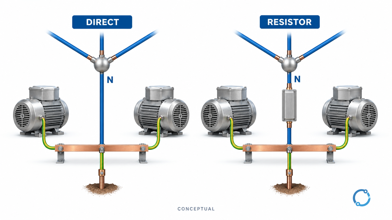
A fault between two phases does not become harmless because the neutral is resistance grounded. Nor does a low first earth-fault current establish acceptable touch voltage, arc-flash risk or continued operation. Those are separate checks.
Resonant and unearthed arrangements require their own network analysis and operating philosophy. They should not enter the shortlist solely because avoiding an immediate outage seems attractive.
Use a resistor calculation only after defining its assumptions
The following example is hypothetical: a balanced 6.6 kV line-to-line source, a direct neutral resistor, a bolted phase-to-earth fault, negligible other series impedance and a target resistor current component of 100 A. These inputs are not recommended plant settings.
The preliminary relationships are:
Vphase = VLL ÷ √3
RN = Vphase ÷ IR
PR = IR² × RN
Here VLL and Vphase are volts, RN is ohms, IR is the resistor current in amperes and PR is the instantaneous dissipation in watts under the assumed fault condition.
For the chosen inputs:
- Vphase = 6,600 ÷ √3 ≈ 3,810.51 V.
- RN ≈ 3,810.51 ÷ 100 ≈ 38.11 Ω.
- PR ≈ 100² × 38.1051 ≈ 381,051 W, or 381.05 kW.
- If that dissipation persisted unchanged for an assumed 10 s, energy would be about 3.81 MJ.
The calculation gives a preliminary resistance and thermal exposure, not a purchasable resistor rating. Voltage tolerance, resistance change with temperature, maximum fault duration, repeat duty, ambient conditions, insulation and grounding-transformer duty can change the specification. A transformer-coupled resistor also requires the appropriate referred impedance; do not use the direct-neutral formula without that conversion.
Recheck the selection for each source state
A permitted operating state needs a defined grounding path and a compatible protection response. Study normal supply, standby supply, parallel sources, split buses and maintenance configurations. Do not let the changeover sequence temporarily create an unintended grounding condition.
Identifiable research on high-voltage shore connections demonstrates why resistor selection changes with connected sources, grounding paths and capacitance. That study concerns a shore-to-ship system; its marine-specific limits and selected resistor values are not generic plant requirements.
The transferable lesson is the study method: evaluate the actual configurations rather than copying a value from a nominal-voltage example. When a new cable feeder or source is added, charging current and earth-fault detection assumptions may change even if the voltage remains the same.
Define verification and fault response before release
Retain a source-neutral diagram, operating-state matrix, fault-study assumptions, resistor or grounding-device duty basis, protection sensitivity checks and monitoring specification.
Approved commissioning should verify the physical path, actual measurements, alarm/trip destinations, source-transfer behavior and the as-left configuration. Testing must be planned by qualified personnel; intentionally creating a ground fault is not an informal way to measure charging current.
Use the separate CT installation and testing workflow for measurement-circuit safety and verification. Do not open an energized CT secondary or bypass the protection system to simplify a test.
Reject or hold a candidate if the load compatibility, charging current, insulation duty, fault response or grounding-source availability remains unresolved. Selection is complete when the installation’s fault behavior is explained and supported across its permitted states—not when the resistor resistance has been calculated.