
Overcurrent relay coordination is a study of which device detects and clears each fault, in which operating state, and with what remaining protection margin. Compare devices on a common current basis, include breaker clearing and uncertainty, and check both minimum and maximum faults. A clean-looking time-current plot at one current is not enough.
This workflow concerns a radial industrial feeder with a downstream relay and an upstream backup relay. The numerical example is deliberately hypothetical. It demonstrates review arithmetic, not settings for a real relay, and it is not a claimed field case.
The study can be developed at a desk. Applying settings and performing trip tests are separate, authorized activities for qualified protection personnel under approved isolation and restoration procedures.
1. Fix the topology, current base and operating states
Begin with an accurate single-line diagram, source contributions, transformer and cable information, current-transformer (CT) ratios, relay functions, breaker timing and protected-equipment limits. Identify every mode that changes the fault path: a bus tie, standby generator, transformer out of service, or an alternative feed.
For each mode, record the maximum load, minimum fault at the remote end and maximum fault near the feeder source. Phase and earth-fault elements need their own fault quantities; a phase fault-current range cannot validate earth-fault sensitivity.
Reclamation FIST 3-9 describes coordination using system diagrams, fault information and protection characteristics. Its December 1991 guidance is useful background, but its historical grading intervals should not be copied into a modern digital-relay study as universal requirements.
Use the separate CT selection guide to check measurement inputs. CT ratio conversion alone does not establish transient performance.
2. Check pickup before comparing time
A delayed element is useful only if it can detect the intended fault. Check that pickup remains above the intended nonfault operating envelope and below the minimum fault quantity it must detect, with the uncertainty required by the study.
Do not resolve a failed sensitivity check by reducing time delay. If the relay never picks up, a faster curve does not provide protection. Likewise, do not remove a needed load or starting allowance merely to obtain a larger separation between curves.
For a simple ratio conversion:
Secondary current = primary current ÷ CT ratio
With an explicitly hypothetical 400/1 A CT, a 600 A primary fault corresponds to 1.5 A secondary, assuming ideal transformation. If a chosen secondary pickup were 1.6 A, the intended element would not pick up in that ideal example. The conversion does not model CT error, saturation, relay filtering or an actual fault waveform.
3. Put relay operation and total clearing on the same timeline
Define the quantities before subtracting them:
| Quantity | Symbol used here | Meaning |
|---|---|---|
| Downstream relay operate time | tD | Time from the study’s fault reference to the downstream trip output |
| Downstream breaker clearing time | tB | Time from that trip output to fault-current interruption |
| Upstream relay operate time | tU | Time from the same fault reference to the upstream trip output |
| Remaining grading gap | G | tU − (tD + tB), before any additional uncounted uncertainty |
All times are in seconds. Do not add breaker time twice when the supplied characteristic already shows total clearing. Conversely, a relay operate curve does not automatically include the downstream breaker.
The engineer must identify what the uncertainty budget contains: timing tolerances, output/contact delays, current decay, element reset behavior and any relevant mechanical or measurement effects. The total required reserve is project-specific.
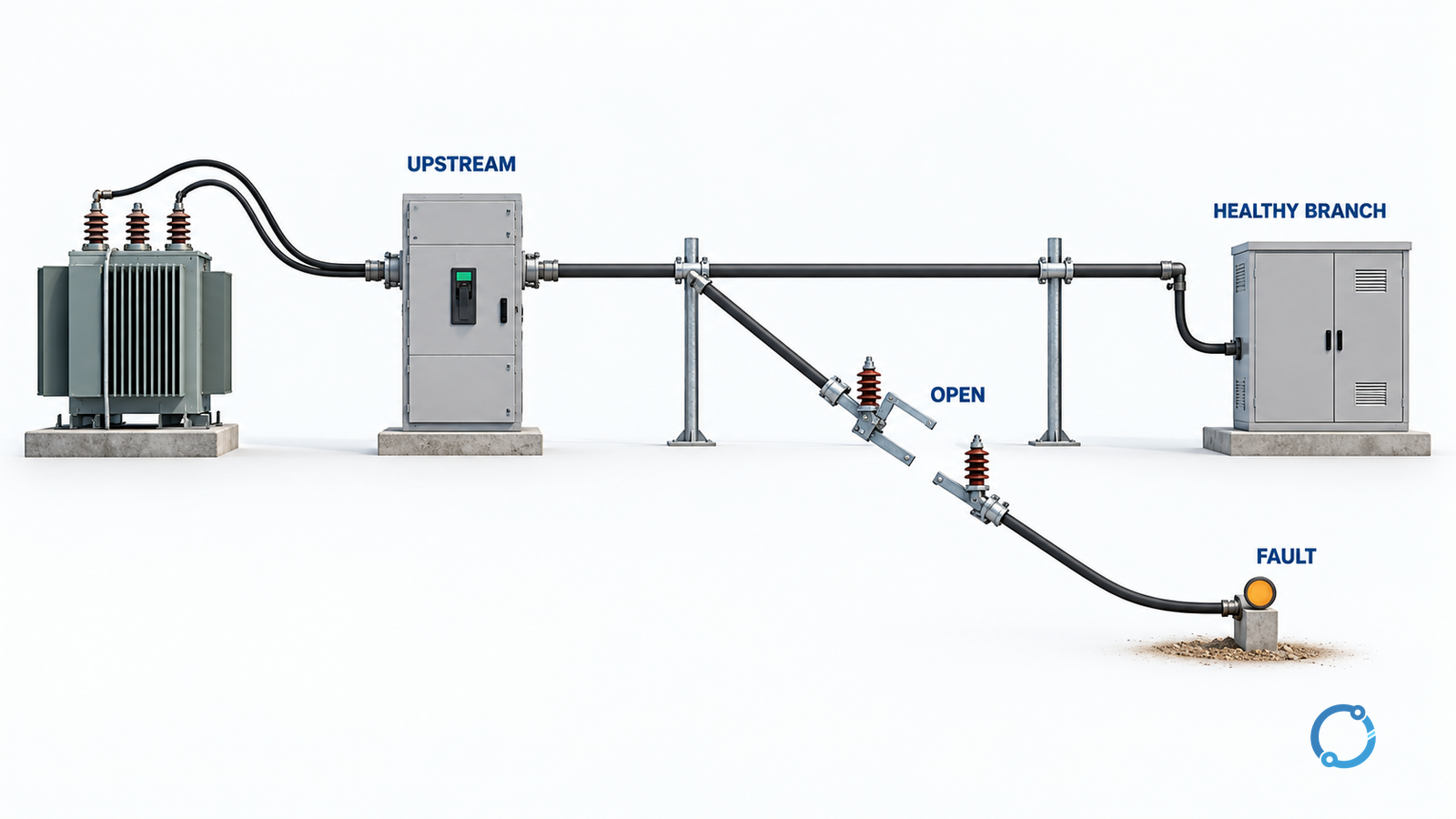
4. Test the margin at more than one fault current
For this separate timing exercise, assume both relays detect every listed fault; the failed 1.6 A pickup counterexample above is not the setting used here. Assume the following artificial desk-study inputs. The downstream breaker clears in 0.060 s, and the reviewer requires a hypothetical 0.150 s remaining reserve. Neither number is a standard-prescribed setting.
| Primary fault current | tD | tU | Downstream total clearing, tD + tB | G | Result against the assumed reserve |
|---|---|---|---|---|---|
| 600 A | 0.080 s | 0.380 s | 0.140 s | 0.240 s | Passes this timing test only |
| 2,000 A | 0.060 s | 0.250 s | 0.120 s | 0.130 s | Insufficient reserve |
| 6,000 A | 0.040 s | 0.100 s | 0.100 s | 0.000 s | No remaining reserve |
At 600 A, the arithmetic is 0.380 − 0.080 − 0.060 = 0.240 s. Judging only that point would miss the failure at higher current.
At 6,000 A, the upstream output coincides with nominal downstream clearing. That does not demonstrate robust selectivity. Review instantaneous elements and the complete clearing bands rather than assuming the delayed curve remains the controlling function.
A candidate revision could change upstream pickup, characteristic, delay or scheme architecture. Each change needs the full fault-range check again. If more delay protects selectivity but violates an equipment withstand or stability limit, delay is not an acceptable standalone fix.
5. Add equipment protection and nonfault behavior
Overlay relevant cable, transformer and motor limits using a common current base and compatible time definitions. Check that the fault is cleared within the applicable withstand envelope. Also evaluate transformer energization, motor starting and other allowed operating conditions without inventing a generic multiplier.
This is where a study may expose an architectural conflict: there may be no setting combination that is both selective and sufficiently fast. A different protection principle, measurement arrangement or circuit segmentation may be necessary.
For low-voltage molded-case or air circuit breakers, use the separate LV selective-coordination workflow. Device tolerance bands and manufacturer-tested combinations are not interchangeable with this relay example.
Fault-clearing time can also affect arc-flash incident energy. A coordination change therefore needs the relevant safety-study review, not only a revised curve plot.
6. Release the study and verify the as-left configuration
Keep one revision-linked record containing the topology, operating modes, fault cases, CT bases, curve definitions, settings, uncertainty budget, equipment limits and unresolved assumptions. Record the reviewer and the specific differences between proposed and previously in-service settings.
Reclamation FIST 6-4 illustrates an agency process that separates proposed settings from as-left records, includes peer review, and preserves setting history. These are useful assurance practices; its internal database and administrative rules are not universal industrial requirements.
Before return to service, approved testing must confirm the intended functions, trip destinations, applicable setting groups and restoration state. A saved settings file does not prove which group is active or that a breaker receives the trip.
Stop when a fault case lacks sensitivity, the timing definitions are inconsistent, the remaining margin is unsupported, the equipment limit is exceeded, or the approved settings cannot be reconciled with the as-left configuration. The finished study must show why the intended device clears first—and why that conclusion survives the operating states actually permitted.