
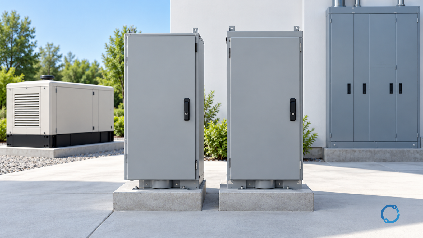
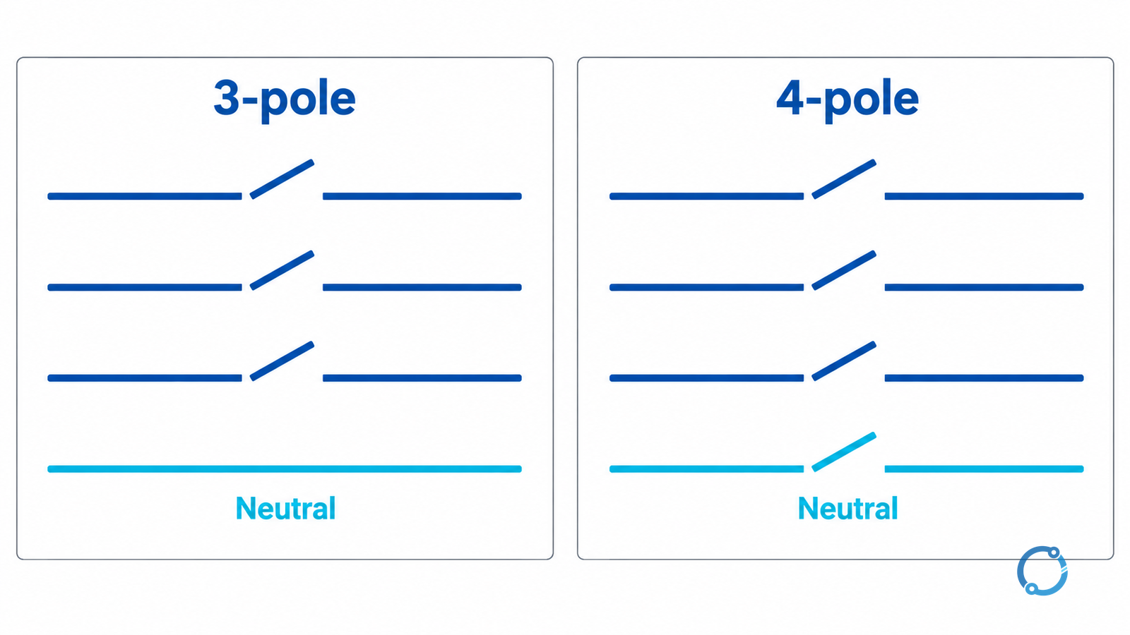
The transfer-switch pole count must follow the neutral and grounding arrangement of the complete system. In a three-phase four-wire system, a three-pole switch transfers three ungrounded line conductors while the neutral follows a separate solid path, if one is provided. A four-pole switch adds a neutral pole so the neutral transfers with the lines. Neither configuration is automatically safer.
The choice depends on whether the alternate source is separately derived, how its neutral is bonded and grounded, the ground-fault return paths in every source state, whether the neutral must remain continuous, and the legally adopted rules. This is a design-review guide, not a wiring instruction. Work requires qualified personnel, an approved isolation plan, and verification that every source is identified.
The National Electrical Code (NEC) is a North American model code, not a global rule. The NEC discussion here applies only where that code and its local amendments have been adopted. Projects in other jurisdictions must use their own applicable standards and approval process.
Start with the neutral path, not the voltage
A transfer-switch “pole” is a current-carrying switching path, not a voltage class. In a three-phase four-wire system, the three line poles normally correspond to the phase conductors. The fourth pole normally corresponds to the neutral. The protective bonding conductor is a separate function and must not be counted as the neutral pole.
That description is only the starting point. A three-pole product may have a solid neutral bar, removable link, or no neutral provision. A four-pole product may have a fully rated neutral pole, reduced rating, or specific contact sequence. Read the terminal schedule and functional diagram; do not infer the arrangement from the catalog heading.
The first drawing should show:
- every normal, alternate, and maintenance source;
- each source winding or transformer connection and its neutral point;
- the neutral path through the transfer switch;
- the neutral-to-ground bond or bonds;
- equipment bonding conductors and the grounding electrode system;
- protective devices and current-sensing locations;
- any bypass, isolation, or parallel operating state.
If the neutral is solid, trace it in every position. If it is switched, trace what remains connected and what happens if its pole does not follow the lines as intended.
The separate neutral switching and linked-pole guide explains conductor function and isolation boundaries. Use it to define what each pole does; use this page to decide whether the fourth pole belongs in the transfer switch.
Decide whether the alternate source is a separately derived system
The phrase “separately derived system” is often used loosely. Ask whether the alternate source is intended to have its own neutral reference and grounding arrangement, or whether the source neutrals are deliberately connected as one common system. The answer is project-specific and must follow the adopted rules. A generator, transformer, or four-pole switch does not establish it alone.
A transformer-fed source may have a winding arrangement that makes the neutral question obvious. A generator neutral may be solidly connected, switched, or intentionally isolated. A second utility feeder may introduce another set of source characteristics. Review the single-line, source data, and bonding design together.
An unswitched neutral can tie source neutral points together even when only one source supplies the load. That may be intentional in a common-neutral system, or it may create an unintended metallic path between source neutrals, particularly when they are derived differently or operate in parallel.
A switched neutral can separate the paths, but only as well as its neutral pole and operating sequence. A four-pole label does not prove the required opening and closing times, short-circuit withstand, or source bonding arrangement.
The source-neutral grounding method is a separate design choice. The neutral earthing system selection guide addresses that connection and fault-current behavior, not whether the switch should have a fourth pole. Use both reviews together, then confirm the locally adopted rules.
Trace the ground-fault return and bonding continuity
A ground fault is not cleared by the word “ground” alone. The current needs a complete return path to its source, and a protective device must detect and clear that path. In a typical grounded system, the path runs from the faulted line through the enclosure or protective bonding conductor, through the bonding and grounding arrangement, and back to the source neutral point.
The transfer switch changes that source-neutral point, impedance, available fault current, and location of current-sensing devices. Trace the return path in:
- normal-source operation;
- alternate-source operation;
- any permitted parallel or closed-transition state;
- a maintenance or bypass state;
- a single-pole failure or stuck-contact condition that the design is required to tolerate.
Keep the protective bonding path continuous. A four-pole switch adds a neutral pole; it does not turn that pole into a protective bonding conductor. The enclosure and associated equipment still need the intended bonding connection. The main bonding jumper guide explains why its location and function must be identified rather than assumed from a neutral bar.
Also check the neutral-to-ground bond in each source state. A second bond downstream can create a parallel return path; a missing or ineffective bond can leave the protective path incomplete. The correct arrangement depends on whether the source is separately derived and on the adopted rules.
Ground-fault sensing deserves its own check. A sensor may measure neutral current, residual current, or a designated grounding path. Switching the neutral can move the sensing boundary or allow current outside the sensor’s coverage. Verify the sensing zone and trip logic in every state.
Compare three-pole and four-pole configurations fairly
The table applies the same questions to both. “Three-pole” here means three switched line poles with a separate solid neutral path, if provided. “Four-pole” means three line poles plus a switched neutral pole. The actual device may differ, so the terminal schedule controls.
| Decision question | Three-pole with a solid neutral path | Four-pole with a switched neutral pole | Evidence needed before accepting the choice |
|---|---|---|---|
| Is a common source-neutral reference intended? | Can preserve a continuous common neutral, but may tie source neutral points together | Separates the neutral path when the pole is open, but does not by itself define the source bonding | Approved single-line, source winding data, and the intended neutral-to-ground bond locations |
| Is the alternate source treated as separately derived? | May be unsuitable if the neutral must remain separated; the result depends on the complete bonding design | May provide the neutral separation the design requires, but only if the neutral pole and sequence are suitable | The written source classification under the adopted rules and the actual transfer-switch functional diagram |
| Are line-to-neutral loads supplied? | The neutral remains on its solid path, but an open or high-impedance neutral still affects the loads | The load neutral is transferred; an open neutral or incorrect contact sequence can shift the neutral reference | Load schedule, neutral current basis, and verified switching sequence |
| Is closed-transition or parallel operation used? | A solid neutral can create a parallel neutral path while both sources are connected | A switched neutral changes the path, but does not automatically solve parallel-source fault coordination | Closed-transition sequence and a fault study for the parallel state |
| Must the neutral be isolated for maintenance? | A solid neutral does not provide neutral isolation at the transfer switch | A switched neutral may provide the intended isolation point, subject to the device rating and procedure | Isolation study, device markings, lockout plan, and qualified verification |
| How does the ground-fault return behave? | Source bonds and a common neutral may create multiple return paths that require review | Equipment bonding must return fault current to the active source bond; neutral switching changes possible parallel paths | Ground-fault path diagram and protective-device coverage for each state |
| What happens to protective bonding? | Must remain continuous and separate from the neutral function | Must remain continuous and separate from the neutral pole | Terminal schedule, enclosure bonding, and as-installed inspection |
The summary is conditional:
- A three-pole configuration with a solid neutral may suit a deliberately designed common neutral whose path is rated for the duty and permitted by the adopted rules. Its main risk is an unintended neutral connection or parallel path.
- A four-pole configuration with a switched neutral may suit sources requiring separate neutral references or neutral isolation at the transfer point. Its main risk is that the fourth pole, rating, and operating sequence add another failure and verification point.
- Neither choice is acceptable merely because the voltage, current rating, or transfer type looks familiar. The neutral and grounding topology must be defensible in every state.
Review switched-neutral operating and failure states
A four-pole switch must be reviewed as a neutral-switching device, not just a three-pole device with an extra contact. Ask for the contact sequence and intended neutral state during normal operation, transfer, bypass, and maintenance. Confirm its fault-current rating, load-breaking duty, and required overlap or delay.
Do not infer “make-before-break” or “break-before-make” from the pole count. Those behaviors belong to the mechanism and control sequence. Manual and automatic switches may differ, and closed transition may create a condition that open transition never creates. The closed-transition transfer-switch guide covers the parallel interval and added coordination evidence.
An open neutral is not a normal operating state. In a four-wire system, losing the neutral reference can shift line-to-neutral voltages, so connected loads may see overvoltage or undervoltage while the lines remain energized. A welded neutral pole can defeat the intended separation. Identify the detection, protective response, and safe state for these conditions.
The same review applies to a solid neutral. A loose connection, incorrect link, or unintended bond can create a path not shown on the drawing. The neutral path must be rated as part of the transfer assembly. If it is not switched, state how neutral isolation will be achieved when required.
Testing belongs to qualified personnel under an approved switching and isolation plan. Do not create a neutral-open condition merely to see what happens to the load. Use the manufacturer’s functional test procedure, the project’s commissioning plan, and the actual source configuration.
Confirm equipment scope, markings, and jurisdiction
The pole decision does not replace the equipment review. UL 1008 is the North American transfer-switch equipment standard. Its public scope covers several automatic, manual, closed-transition, hybrid, fire-pump, bypass/isolating, softload, and service-entrance types up to 1000 V. It excludes certain double-throw switches for optional standby systems and transfer switches over 1000 V. Scope is not proof that a product is listed.
The current dedicated IEC transfer switching equipment standard is IEC 60947-6-1:2026. Its public scope covers equipment used to transfer a load between sources at up to 1000 V AC or 1500 V DC. It also identifies annex material for bypass/isolation, closed-transition, stand-alone controllers, and fire-pump applications. Confirm the exact edition and product scope; a catalog title is not a substitute for marking and test evidence.
IEC 60947-3:2020+AMD1:2025 CSV covers switches, disconnectors, switch-disconnectors, and fuse-combination units in distribution and motor circuits up to 1000 V AC or 1500 V DC. It describes a switching component, not dedicated transfer switching equipment performance, so it cannot establish complete transfer-switch or neutral-pole suitability.
The NEC is a North American model code published by NFPA. UL reports that the 2026 edition was issued on August 20, 2025, with an effective date of September 9, 2025, and NFPA lists that edition as current. That does not make it legally adopted in every project. Confirm the edition, amendments, interpretations, utility requirements, and authority having jurisdiction before fixing the pole arrangement.
Verify the markings that matter to the decision:
- rated voltage, frequency, and continuous current;
- short-circuit withstand and closing ratings;
- neutral-pole rating and switching duty, where a fourth pole is used;
- transfer type and any closed-transition rating;
- bypass and isolation functions;
- listing or certification evidence for the complete assembly;
- the manufacturer’s terminal schedule and operating sequence.
Apply a release gate
Do not release the pole selection until the following evidence is present:
- An approved single-line showing every source, neutral, bond, grounding electrode, and protective device.
- A written determination of whether the alternate source is treated as separately derived under the adopted rules.
- A neutral-path decision: solid, switched, isolated, or not provided, with the reason stated.
- A ground-fault return and sensing check for normal, alternate, parallel, bypass, and credible failure states.
- Evidence that the protective bonding path remains continuous and separate from the neutral function.
- The neutral-pole rating, contact sequence, and failure behavior for a four-pole option; the solid-neutral rating and isolation method for a three-pole option.
- Equipment scope, markings, assembly ratings, and certification evidence for the exact product.
- The adopted code edition, local amendments, utility requirements, and approval path.
- A functional test and as-left record completed by qualified personnel.
If any item is unresolved, the correct state is hold. A three-pole switch is not a safe default, and a four-pole switch is not a universal upgrade. The defensible answer is the configuration whose neutral, grounding, bonding, fault-return, and equipment evidence agree in every permitted state.