
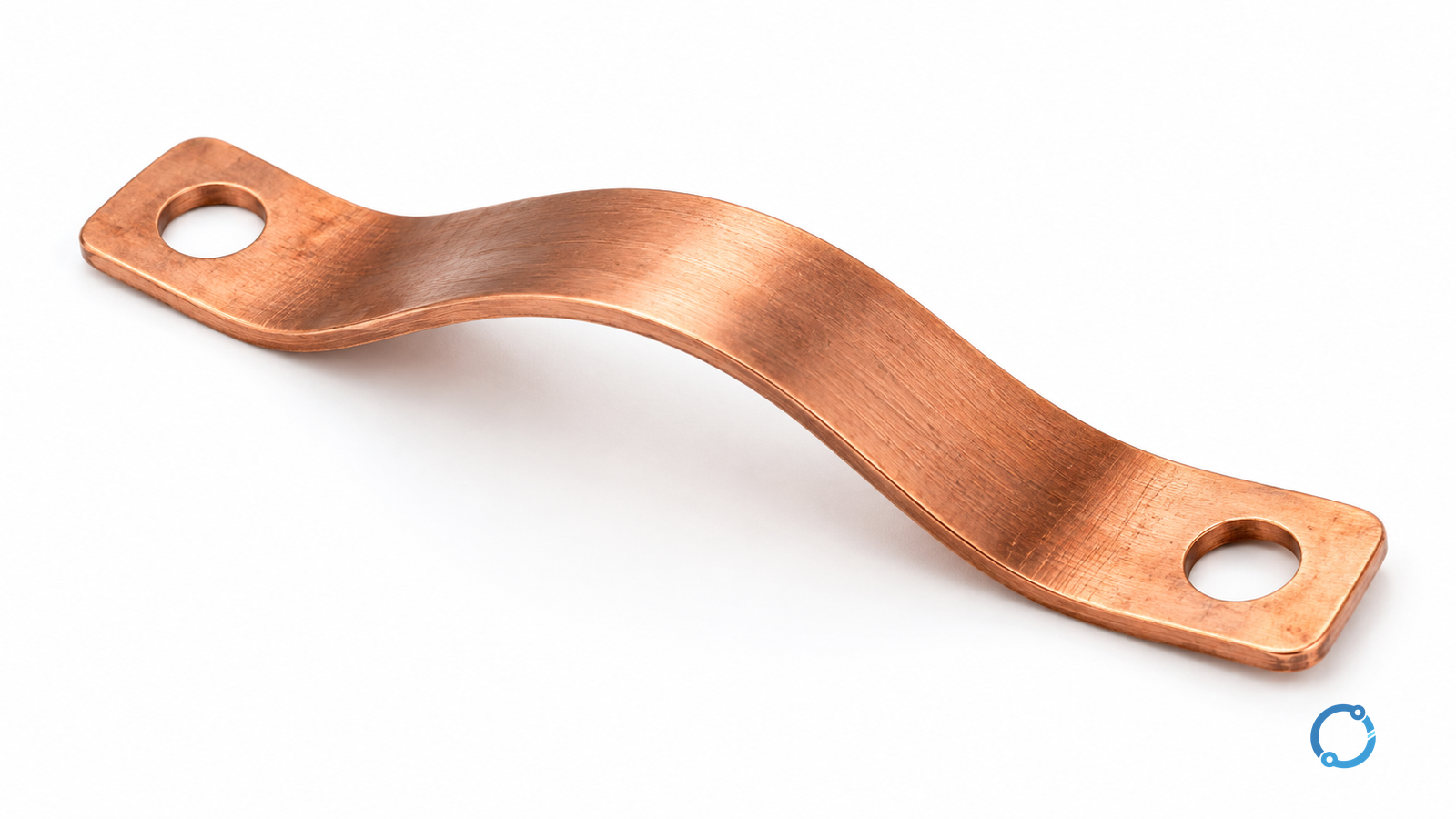
The main bonding jumper connects the grounded service conductor to the required protective bonding arrangement at the service. To check its size, first establish that service location, then identify whether the jumper is part of an evaluated equipment assembly or a field-installed conductor. A breaker-ampere-to-wire-size shortcut cannot resolve those questions.
For a field wire, the useful output is a record connecting the applicable code edition, service-conductor arrangement, conductor materials, sizing provision and actual termination. This article uses U.S. National Electrical Code (NEC) terminology. It is a design and inspection preparation guide, not permission to open service equipment or change a neutral bond.
Identify the conductor by its job
Several conductors can appear near the same service enclosure without having the same sizing rule.
| Item | Function to identify | Why it is not interchangeable with the main bonding jumper |
|---|---|---|
| Main bonding jumper | Service grounded-conductor connection to the protective bonding arrangement | It belongs to the service bonding function |
| System bonding jumper | Corresponding bonding function at a separately derived source | The source and permitted connection arrangement must be established separately |
| Equipment grounding conductor | Protective path with the circuit to exposed conductive equipment parts | It is not a normal neutral-current path |
| Grounding electrode conductor | Connection to the grounding electrode system | Earth-electrode connection and service fault-return bonding are different functions |
| Grounded circuit conductor, often the neutral | Circuit conductor intentionally grounded by the system design | It can carry normal load current and must not be treated as an equipment grounding conductor everywhere |
The International Association of Electrical Inspectors’ 2021 grounding and bonding explanation distinguishes main from system bonding jumpers and discusses the field-wire sizing route through NEC 250.28(D) and Table 250.102(C)(1). That explanation is edition-dependent technical guidance; verify the locally adopted NEC text and amendments before approving a size.
An earth-electrode resistance measurement does not verify this entire bonding arrangement. Likewise, industrial neutral-earthing system selection addresses source fault behavior, not a universal rule to connect every neutral bar to its enclosure.
Establish where the service actually ends
Read the one-line diagram and service-equipment identification together. Do not identify the service disconnect merely by the largest handle or by a panel being the first enclosure visible inside a building. Upstream disconnects and the actual supply arrangement matter.
UL’s Panelboard Application Guide explains service-use markings and supplied neutral-bonding provisions. It also distinguishes service use from downstream use, where installing the service bonding means can be inappropriate. Read the actual equipment markings and instructions rather than transferring a bonding screw from a similar-looking panel.
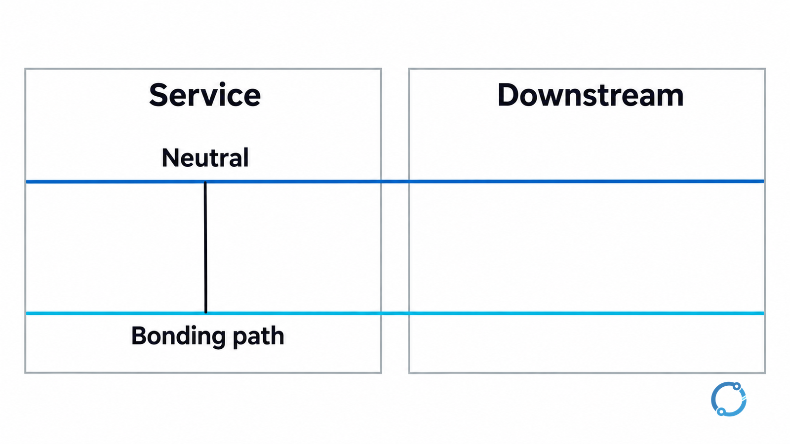
Multiple service enclosures, separately derived transformers and switched-neutral arrangements need their own applicable analysis. “Bond once” is not a complete design rule for every multi-source installation. The review must identify the actual service and each separately derived system before deciding what belongs in a particular enclosure.
Separate a supplied assembly jumper from a field wire
A supplied strap, bus or bonding screw can be part of the equipment’s evaluated construction. Its acceptability depends on the identified assembly, service-use configuration and instructions. It is not appropriately checked by measuring its appearance against a generic copper-wire chart.
A missing part requires the correct approved replacement or an engineered, permitted repair. An arbitrary screw, a convenient enclosure fastener or an improvised strap does not establish the required function.
For a field-installed wire, collect the conductor-area and material information needed by the adopted sizing provisions. Do not substitute the grounding-electrode conductor table or a downstream equipment-grounding conductor table merely because all three items are informally called “ground wires.”
Build the sizing record before choosing the wire
Use this review worksheet to expose missing inputs. It organizes the engineering review; it is not an additional NEC checklist.
| Input | What to record | Hold the selection when… |
|---|---|---|
| Applicable rules | Adopted NEC edition, amendments and relevant service configuration | The drawing and proposed rule use different editions or scopes |
| Jumper identity | Main, system or supply-side bonding function; exact enclosure | The conductor’s function is unresolved |
| Equipment evidence | Assembly identity, supplied bonding means and permitted installation | The proposed part cannot be traced to the assembly |
| Service conductors | Material, size and number in parallel for each phase | Only breaker amperes or a total cable count is available |
| Field-jumper basis | Applicable table/notes, selected material and any different-material treatment | A table row is selected without checking its notes |
| Connection acceptance | Permitted conductor range, attachment method and specified installation requirements | The selected conductor cannot be terminated as permitted |
Parallel conductors illustrate why the input matters. In a hypothetical three-phase service with two 350 kcmil conductors in parallel per phase, the area represented by one phase is 2 × 350 = 700 kcmil. It is not the sum of all six phase conductors, 2,100 kcmil. Here kcmil means thousand circular mils, an area unit, not amperes.
That arithmetic establishes an input for the applicable review, not a final jumper size. Confirm which conductors serve the enclosure, the adopted table and notes, jumper material, and any multiple-enclosure provisions. Do not convert an aluminum service-conductor area into a copper jumper by treating the materials as identical.
Verify installation without creating a new hazard
Checking a design record is different from working inside service equipment. Opening the main disconnect can leave incoming parts energized. For covered U.S. general-industry work, the Occupational Safety and Health Administration (OSHA) rule 29 CFR 1910.333 establishes deenergization and qualified-person verification requirements. The responsible team must establish isolation, lockout/tagout, verification and required personal protective equipment under the applicable procedure.
Use the approved inspection and test method to verify the installed protective path. A continuity indication alone cannot establish conductor size, acceptable attachment or the absence of an unintended downstream bond. Do not loosen a bond while energized to investigate current or noise. The separate computer-grounding diagnostic guide explains why removing a protective connection is not an acceptable interference experiment.
The completed record should identify the service, jumper function, assembly or field-wire basis, selected component/conductor, connection evidence and inspection acceptance. If the service arrangement or sizing basis remains unknown, keep the item open for the responsible designer and authority having jurisdiction rather than filling the gap with a familiar wire size.