
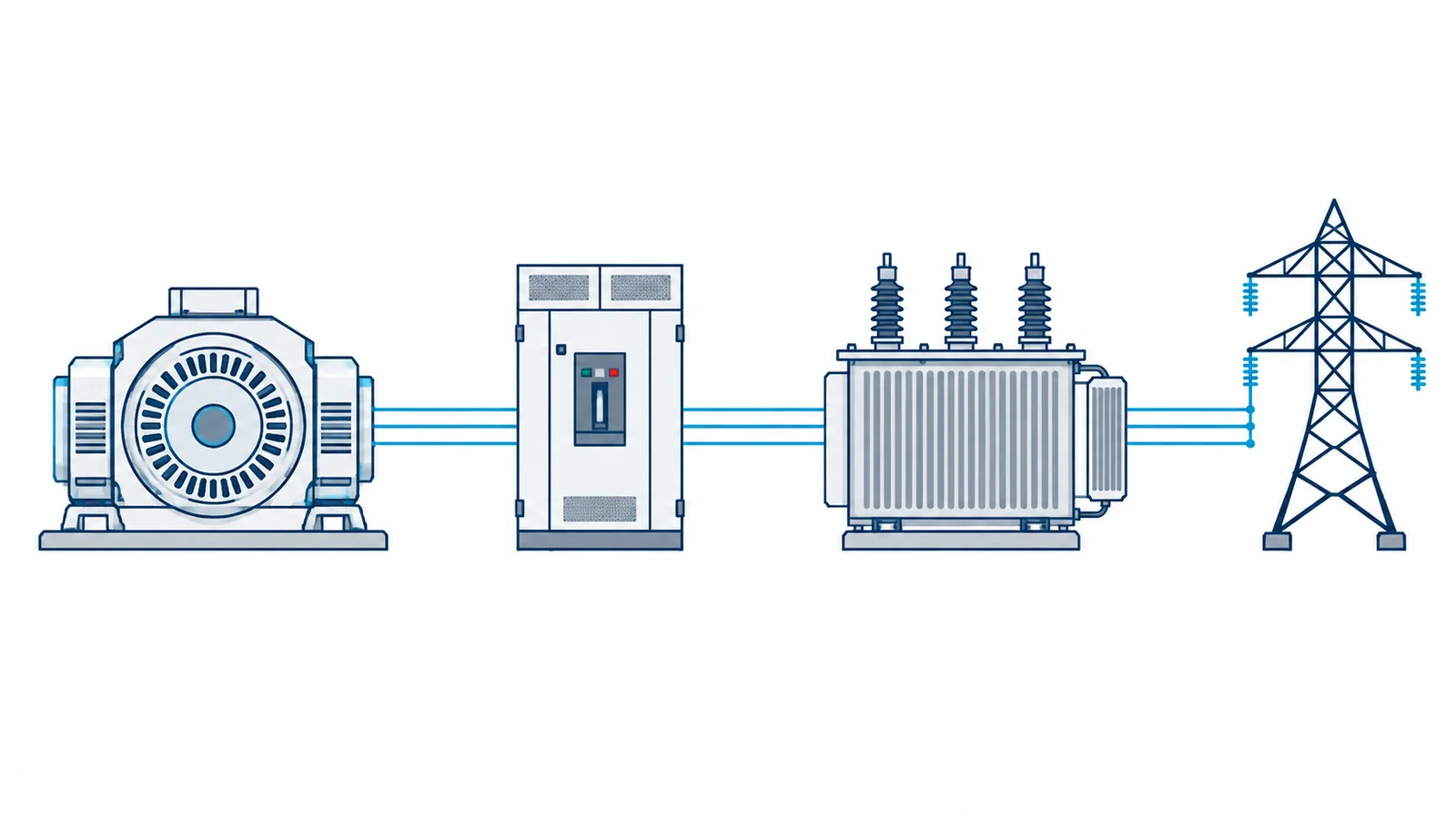
A medium-voltage generator circuit breaker (GCB) cannot be specified from one symmetrical short-circuit kA value. Study faults fed from the generator and faults fed from the power system through the step-up transformer, at the actual breaker location. Compare the resulting current, asymmetry, current-zero behavior and transient recovery voltage (TRV) with ratings and test evidence for the proposed GCB. The relevant device standard is IEC/IEEE 62271-37-013:2021, whose IEC catalog notes a corrected version in 2025; it specifically addresses AC generator circuit breakers above 1 kV up to 38 kV. Ordinary MV breaker ratings do not automatically establish this duty.
This is a study-input and rating-verification guide for power-plant engineers. It is not a finished short-circuit calculation, protection setting, or procurement approval. Actual results depend on generator and transformer data, network equivalents, operating modes, protection clearing time, and the applicable project specification.
Why the two directions differ
Place the GCB between the generator terminals and the generator step-up transformer in the one-line. For a fault on the transformer or network side of the breaker, the generator may supply the fault through the GCB. For a fault on the generator side, the external system may feed it back through the transformer and GCB. The two cases have different source impedances, dynamic behavior and recovery-voltage conditions. A one-line that simply gives “the bus fault level” hides that distinction.
| Study case | Main source through the GCB | Model inputs to preserve | Rating question |
|---|---|---|---|
| Transformer-side fault | Generator | Subtransient/transient generator data, excitation response, decrement, fault duration | Can the GCB interrupt the resulting generator-source duty? |
| Generator-side fault | Power system through step-up transformer | Network equivalent, transformer impedance and taps, operating topology | Can the GCB interrupt system-source duty and withstand its recovery voltage? |
| Multiple generator/transformer arrangement | More than one credible source path | Parallel units, tie state, transformer configuration | Which arrangement creates the governing duty? |
| Out-of-phase or abnormal switching, if credible | System and generator voltage difference | Synchronizing, controls, protection and operating scenario | Is the special switching duty covered by the tested application? |
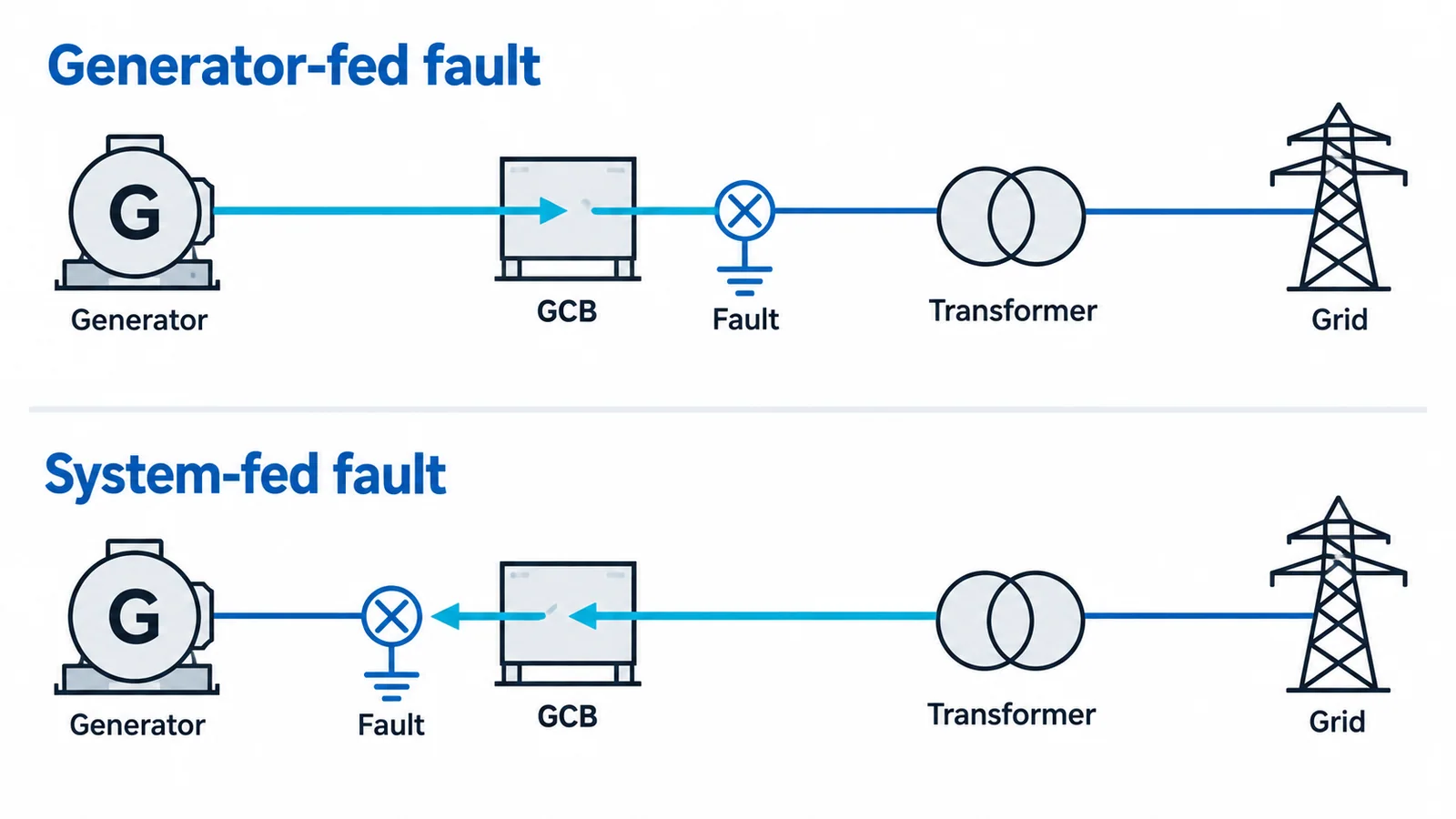
The 2021 standard’s official scope explicitly includes applications with multiple generators connected to one step-up transformer and other special plant configurations. It also discusses capacitor effects on prospective TRV for certain duties. Those details are a warning against silently extending a simple one-generator diagram to every plant.
Breaking current is a time-dependent duty
The study must produce current at the prospective contact-parting and interruption conditions, not just the initial symmetrical current at fault inception. A generator’s contribution can change as its electromagnetic transients decay and excitation acts. The DC component and its decay influence asymmetry and may delay current zero. The external system’s contribution has a different source model and X/R behavior. The GCB application review therefore needs the current waveform or standard-defined duty representation for each credible case, along with the clearing and operating sequence assumptions.
Do not convert a three-phase fault MVA into kA and call it a breaker selection. The dimensional relationship
I_sym = S_sc / (sqrt(3) × U_LL)
relates a specified symmetrical apparent fault power to line current at the same voltage. With MVA and kV, it yields kA. It says nothing by itself about the generator’s decrement, DC offset, contact-parting time, delayed current zero, TRV or tested GCB duty. A breaker with a numerically larger nameplate kA is not necessarily suitable for every one of those conditions.
The capacity check is a bundle of comparisons
Request a study report that makes the following explicit:
- System model and operating envelope: generator rating and reactances, transformer data, network equivalents, grounding, parallel units, tie positions, and credible minimum/maximum configurations.
- Fault locations and direction: faults on both sides of the GCB, including the modes that govern generator-source and system-source interruption.
- Current and timing: symmetrical and asymmetrical duty at relevant times, protection and breaker operating sequence, and any delayed-current-zero concern.
- Recovery voltage: prospective TRV across the opening contacts, including the relevant circuit capacitances and special plant topology. TRV is not interchangeable with steady-state rated voltage.
- Other equipment constraints: continuous current, short-time withstand, insulation level, temperature/environment and the assembled switchgear interface.
- Documented comparison: show each study duty beside the specific GCB rated/tested capability and identify any extrapolation or margin assumption requiring manufacturer and project review.
The standard scope is broader than a single breaking-current row. IEC 62271-100:2021, amended in 2024 covers general AC circuit breakers above 1 kV, but generator circuit breakers have the dedicated IEC/IEEE 62271-37-013 application framework. For ordinary feeder breakers, the MV circuit-breaker ratings guide addresses the general rating vocabulary; it should not replace this generator-specific study.
A specification-ready result
A defensible GCB specification identifies the standard and edition, plant configuration, source-side fault cases, current and TRV results, operating sequence, environmental assumptions, and evidence that the proposed breaker/system covers each duty. If the study lacks a generator-source waveform, a system-source case or a TRV assessment, the selection is incomplete even when the headline breaking-current rating appears generous.
For the broader switching-device context, see Medium-Voltage Switchgear Switching Devices. Qualified power-system and equipment specialists should resolve any application outside the published ratings or tested configuration before purchase or commissioning.