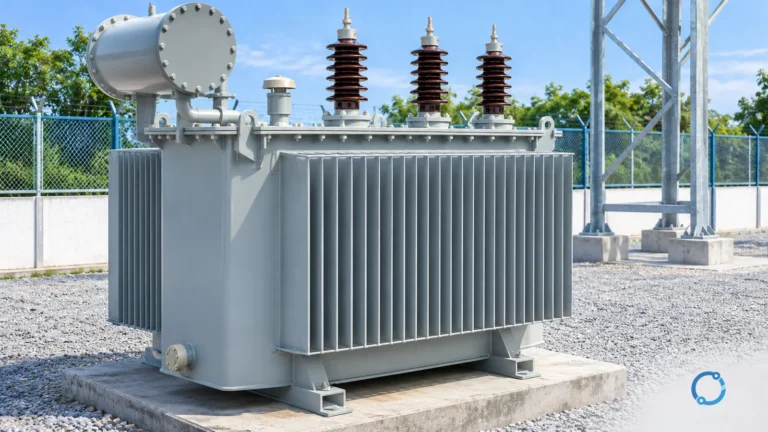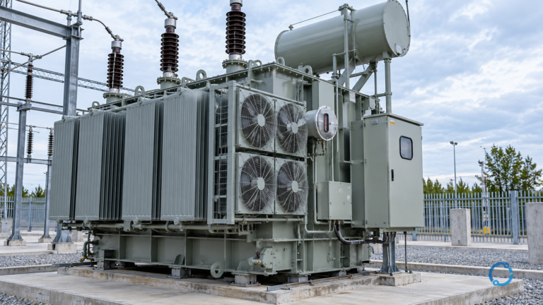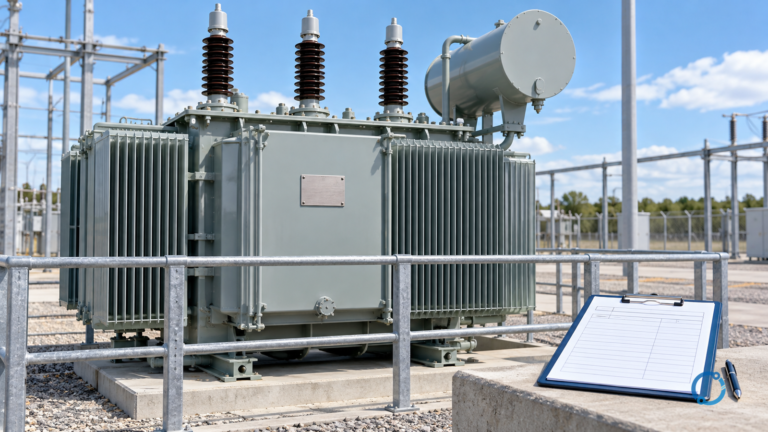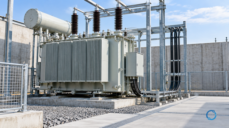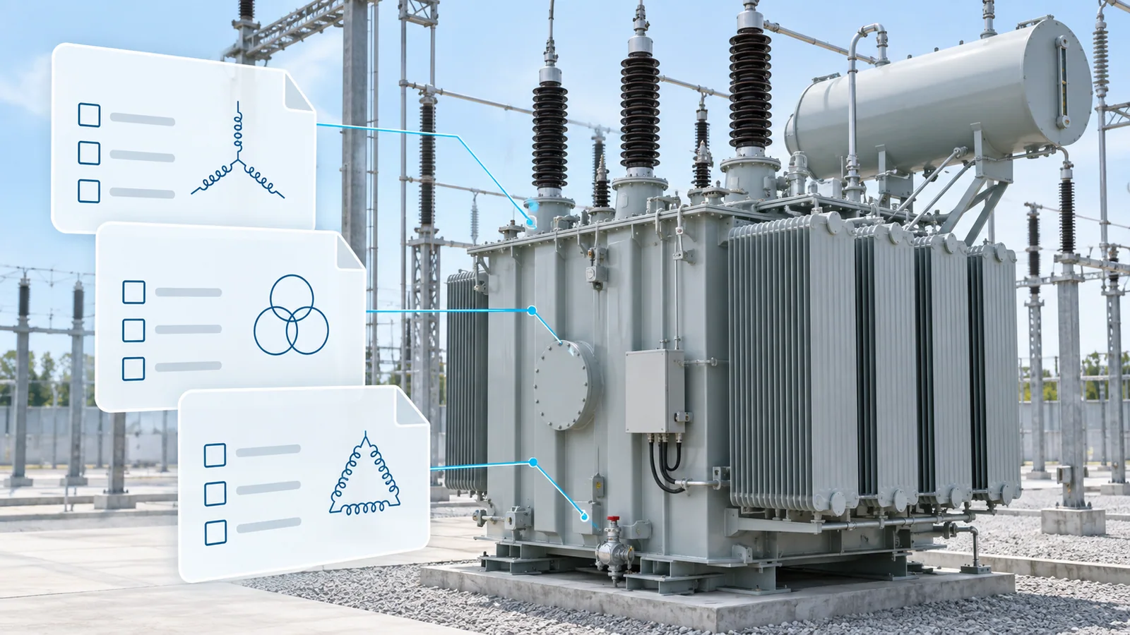
“Comply with IEC 60076” is not a complete transformer specification. IEC 60076-1 supplies the general framework, while other parts address thermal performance, insulation and dielectric tests, short-circuit withstand and specialist applications. The purchaser still must define the system, service conditions, rated quantities, vector group, tapping, impedance, losses, cooling, sound, accessories, tests and required documents.
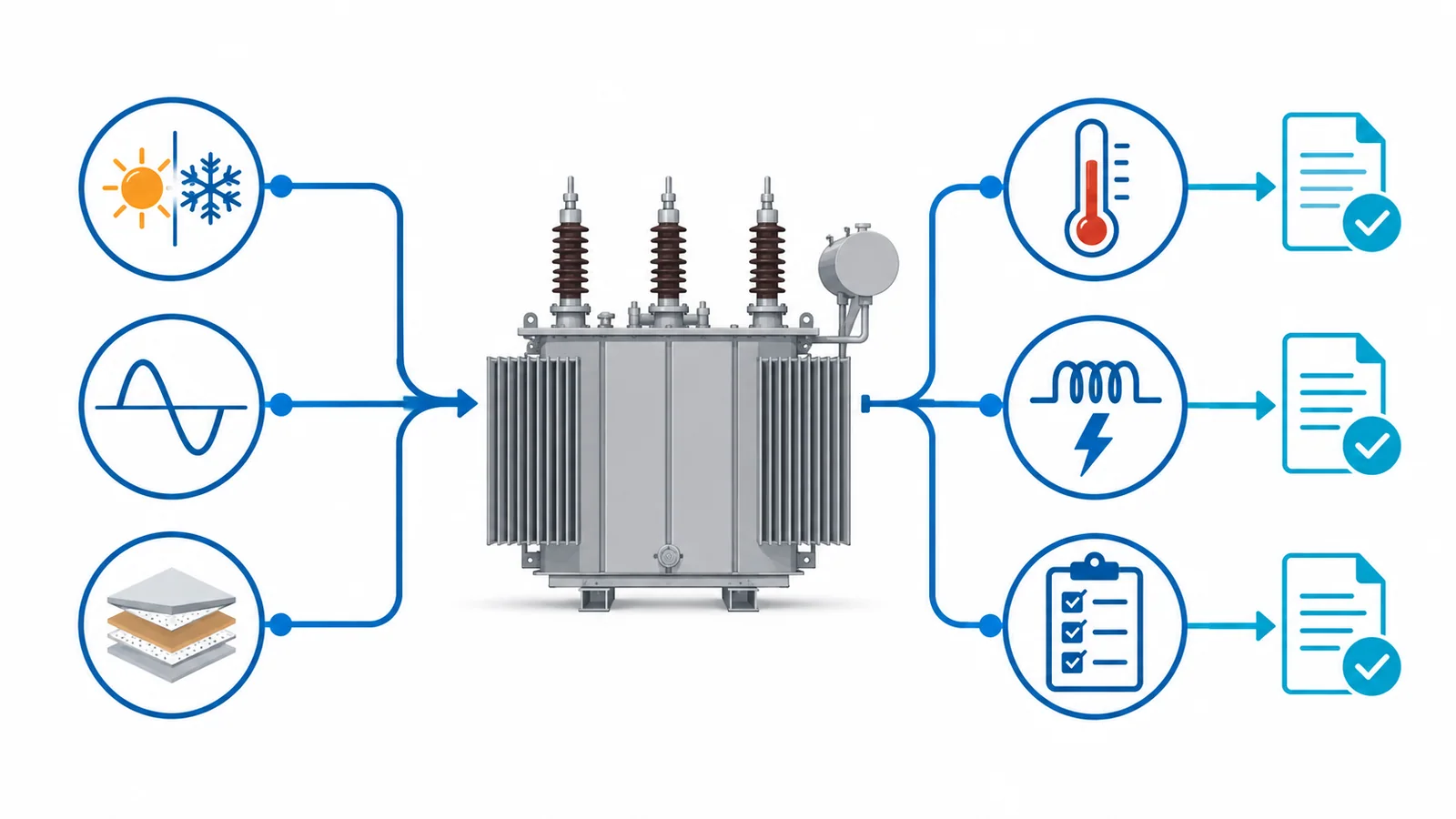
The most reliable approach is a two-column specification: one column states the required value or choice; the other states the evidence the supplier must return. That prevents project decisions from disappearing inside a standards reference.
Scope
This checklist is for a three-phase liquid-immersed power or distribution transformer purchased on an IEC basis. It is a structure for an enquiry or technical schedule, not a substitute for the complete standards or a project-specific engineering review.
IEC 60076-1:2011 applies generally to single- and three-phase power transformers, including autotransformers, except identified small and special categories with their own standards. Its official scope includes ratings, service conditions, tests, transport, liquid preservation, monitoring and environmental or safety considerations.
Dry-type transformers, converter transformers, wind-turbine units, reactors and other specialist equipment need their applicable product parts and may need a different schedule.
1. Identify the transformer and its duty
Start with the function, not the catalog family.
Record:
- project, site and transformer identifier;
- two-winding, multi-winding or autotransformer;
- step-down, step-up, intertie or generator duty;
- indoor or outdoor installation;
- continuous, cyclic, emergency or intermittent loading;
- parallel operation with existing units;
- intended service life basis and maintenance philosophy;
- applicable IEC 60076 parts and project specifications;
- local legal, environmental, fire and efficiency requirements.
If the unit will parallel with another transformer, provide the existing unit’s ratio, vector group, impedance, tap range and control philosophy. “Suitable for parallel operation” is not a self-defining requirement.
2. Define service conditions
The manufacturer needs conditions that change insulation, cooling, corrosion, tank design or accessories:
- site altitude;
- minimum, average and maximum ambient temperatures;
- solar exposure and wind assumptions;
- humidity, condensation, salt, dust or corrosive atmosphere;
- seismic requirement;
- installation clearances and restricted airflow;
- transport route, acceleration limits and dimensional constraints;
- storage duration and preservation;
- system harmonics and DC current exposure;
- unusual vibration or nearby heat sources.
State whether conditions fall within the standard’s normal service conditions. If not, identify them as special service conditions and require the supplier to state design consequences.
3. Specify rated power and loading
For each winding and cooling stage, state:
- rated power in kVA or MVA;
- number of phases and frequency;
- loading profile;
- expected load power factor where relevant;
- harmonic spectrum or nonlinear load duty;
- emergency loading requirement and duration;
- auxiliary loads supplied by tertiary or dedicated winding;
- future uprating assumptions.
Do not select rated power solely from peak kW. Account for power factor, harmonic heating, cyclic duty, redundancy criteria and permitted temperature. If emergency loading beyond nameplate is required, specify the loading basis and required thermal evidence rather than adding an undefined “20% overload.”
4. Set voltages, insulation and system grounding
For every winding, provide:
- rated voltage;
- highest voltage for equipment, Um;
- system grounding method;
- neutral connection and insulation;
- frequency;
- expected voltage variation;
- lightning and switching environment;
- required insulation levels and dielectric tests;
- external clearances where purchaser-defined.
IEC 60076-3:2013+A1:2018 addresses transformer insulation requirements, dielectric tests and external clearances in air. The official publication page describes test requirements by winding/terminal and minimum dielectric test levels. The purchaser should state the system data from which insulation coordination is derived; the manufacturer should return the applied levels and test program.
Do not infer the complete insulation specification from rated winding voltage alone.
5. Define connection, vector group and neutral duty
Specify:
- winding connection and vector group;
- phase sequence and terminal markings;
- neutral brought out or internally connected;
- neutral current duty;
- grounding-resistor or reactor interface;
- zero-sequence requirements where system studies depend on them;
- tertiary winding rating and use;
- phase displacement relative to existing units.
A vector-group mismatch can prevent parallel operation or create unintended circulating current and grounding behavior. Treat it as a controlled system parameter.
6. Specify tapping and voltage regulation
For an off-circuit tap changer or on-load tap changer, state:
- tapped winding;
- total tap range;
- step size and number of positions;
- principal tap;
- constant-flux or variable-flux basis where relevant;
- off-circuit or on-load operation;
- control mode, line-drop compensation and remote interfaces;
- tap position indication;
- parallel-control requirements;
- mechanical and electrical endurance expectations;
- maintenance and spare-parts requirements.
Provide the expected system voltage range and regulation objective. The manufacturer should return voltage ratios, currents and impedance behavior across the relevant tap positions.
7. Set impedance and short-circuit requirements
Specify the required short-circuit impedance at a reference temperature, rated power and named tap, including tolerance or system-study band. Then check:
- available fault current on each side;
- upstream source impedance;
- motor contribution and parallel transformers;
- protection clearing times;
- permissible voltage drop and regulation;
- load sharing between parallel units.
Higher impedance reduces prospective fault current but increases voltage drop and reactive demand. Lower impedance improves regulation but can raise fault duty. The chosen value is a system coordination decision.
IEC 60076-5:2006 addresses the ability of power transformers to withstand overcurrents caused by external short circuits and describes thermal calculations plus special-test or theoretical-evaluation approaches for dynamic effects. State the project fault assumptions and required evidence; do not simply request “short-circuit proof.”
8. Define losses and efficiency
State:
- guaranteed no-load loss;
- guaranteed load loss at the specified reference temperature and rated current;
- auxiliary cooling power;
- loss capitalization or evaluation formula;
- measurement tolerances and acceptance treatment;
- applicable legal efficiency requirement and jurisdiction;
- harmonic or non-sinusoidal loading basis.
Keep guaranteed values, evaluation values and regulatory metrics distinct. If bids are evaluated on total owning cost:
Evaluated cost = purchase price + A × no-load loss + B × load loss + C × auxiliary loss
where A, B and C are purchaser-defined monetary factors based on the project’s energy and loading assumptions. State units and currency. The formula compares bids; it does not change the guaranteed test values.
9. Define thermal performance and cooling
IEC 60076-2:2011 applies to liquid-immersed transformers, identifies cooling methods, defines temperature-rise limits and gives temperature-rise test methods.
Specify:
- cooling designation and stages;
- rated power at each stage;
- ambient basis;
- top-liquid and winding temperature-rise requirements;
- hot-spot treatment where required;
- radiator arrangement and isolation valves;
- fan/pump redundancy and supply;
- controls, alarms and loss-of-cooling behavior;
- temperature indicators and remote signals;
- temperature-rise test requirement and loading condition.
Do not combine a special ambient condition with standard temperature-rise values without stating the permitted absolute temperatures and design basis.
10. Sound, vibration and mechanical interfaces
Provide:
- guaranteed sound-power or sound-pressure requirement and measurement basis;
- whether cooling equipment is included;
- site tonal/noise limits;
- foundation and center-of-gravity data;
- wheel, skid or base arrangement;
- jacking, lifting and pulling points;
- terminal and cable-box forces;
- bushing orientation and phase spacing;
- overall dimension and mass limits;
- oil containment and fire-separation interfaces.
State the measurement standard and acceptance location for noise. “Low noise” cannot be tested.
11. Liquid, tank and preservation system
Specify:
- insulating liquid type and required standard;
- mineral-oil or alternative-fluid fire/environmental constraints;
- sealed, conservator or other preservation system;
- pressure/vacuum design expectations;
- corrosion category and coating system;
- drain, sampling and filter valves;
- oil level, pressure and gas-detection devices;
- leak and pressure test evidence;
- site filling, filtration and commissioning scope.
Environmental claims require project-specific evidence. Do not infer biodegradability, fire point or compatibility from a generic fluid name.
12. Protection, monitoring and accessories
Create a point list with function, contact rating, alarm/trip logic and interface. Typical items may include:
- liquid and winding temperature indication;
- pressure relief;
- sudden-pressure or gas-actuated device where applicable;
- liquid level;
- fan and pump control;
- marshalling kiosk;
- current transformers;
- tap-changer controls;
- online monitoring interfaces;
- space heaters and lighting;
- terminal boxes and gland plates.
Specify the interfaces; do not dictate unnecessary proprietary architecture. Protection settings belong to the system protection study, not solely to the transformer purchase order.
13. Tests and acceptance evidence
Divide requirements into:
- routine tests required for each unit;
- type tests required by the specification or accepted previous evidence;
- special tests requested for the project;
- site tests and commissioning checks.
For every requested test, state:
- applicable standard and edition;
- test object and tap/cooling condition;
- witness, hold or review point;
- acceptance criterion;
- report format and due date;
- treatment of a failed result.
Avoid checking every optional test by default. Each test should close a defined technical risk.
Requirement-to-evidence matrix
| Requirement group | Purchaser states | Supplier returns |
|---|---|---|
| Service | ambient, altitude, installation, special conditions | design basis and deviations |
| Ratings | power, voltage, frequency, duty | guaranteed schedule |
| Connection | vector group, neutral, phase sequence | winding/terminal diagram |
| Insulation | Um, grounding, withstand levels | test levels and dielectric program |
| Thermal | cooling stages, ambient, temperature limits | guaranteed rises and test method |
| System | impedance target, fault duty, parallel data | impedance values and withstand evidence |
| Losses | guaranteed limits and evaluation method | guaranteed values and test results |
| Mechanical | interfaces, dimensions, mass limits | outline drawing and load data |
| Accessories | functions, contacts, protocols | point list and schematics |
| Tests | routine/type/special/site scope | procedures, certificates and reports |
| Lifecycle | manuals, spares, preservation, training | document register and recommended resources |
Copy-ready enquiry checklist
Before issue, confirm the schedule contains:
- transformer type, quantity and applicable standards;
- service and transport conditions;
- rated power by cooling stage;
- winding voltages, Um, frequency and grounding;
- vector group, neutral and tertiary data;
- tap-changer type, range, step and control;
- impedance value, reference tap and tolerance;
- loss guarantees and evaluation method;
- thermal limits and cooling redundancy;
- insulation levels and dielectric tests;
- external short-circuit duty and evidence;
- sound requirement and measurement basis;
- liquid, tank and preservation system;
- bushings, cable boxes and mechanical interfaces;
- protection, monitoring and communication points;
- routine, type, special and site tests;
- drawings, calculations, manuals and data-file formats;
- deviations schedule and document precedence.
Require bidders to return a completed schedule and a separate deviation list. Silence should not be interpreted as acceptance of an ambiguous clause.
Bottom line
IEC 60076 is a standards framework, not the purchaser’s missing data sheet. Define the actual system and service conditions, state measurable requirements, map specialist topics to the relevant parts, and require evidence for every guarantee. A complete schedule produces comparable bids and testable acceptance; a one-line compliance statement does not.
Once the technical schedule is clear, use the power-transformer manufacturer overview as a starting point for supplier research, not as evidence of compliance. The transformer feeder-sizing workflow covers a separate system-interface question.