
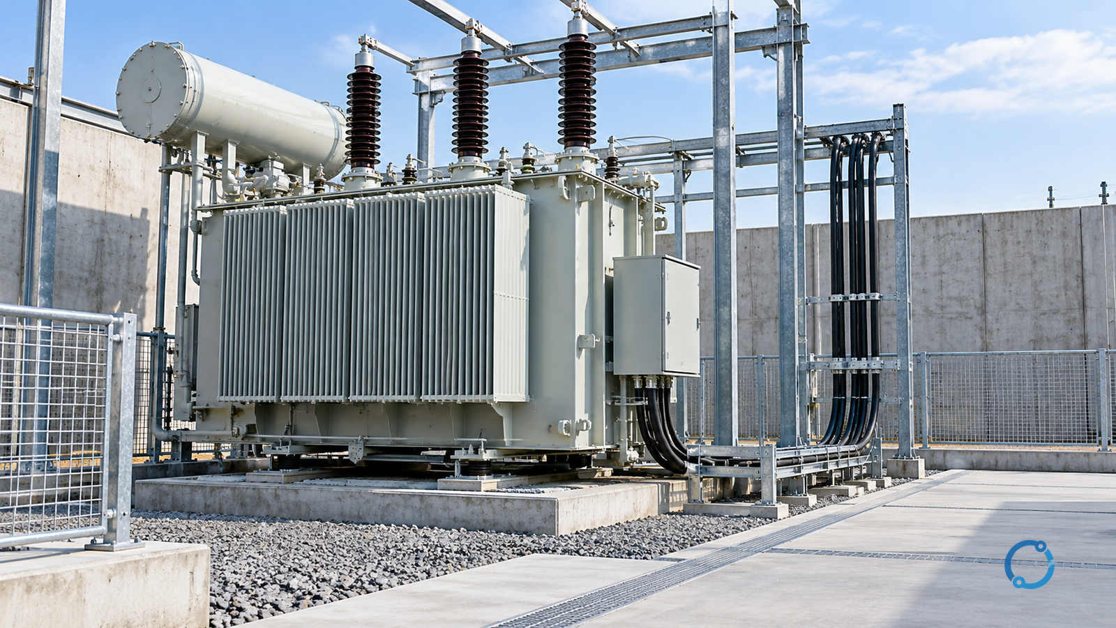
Prepare a transformer for installation by turning the approved design, the received unit and the completed site work into one evidence record. The record must reconcile identity and configuration, condition on arrival, foundation and access, enclosure and environment, insulation or liquid state where applicable, terminal and bonding interfaces, protection and control connections, and the final handover state.
That record supports an installation release. It is not permission to energize the transformer. Energization belongs to a later, separately authorized commissioning step with its own switching program, protection status and acceptance evidence.
This guide covers the preparation journey before that step. It applies generally to distribution and power transformers, including liquid-immersed and dry-type units where the relevant checks apply. The exact method, test value, torque, clearance, fluid limit and accessory setting remain specific to the approved design, product instructions, local rules and competent person performing the work.
Work boundary: Installation and testing can expose people to electric shock, stored energy, induced voltage, moving plant and hazardous materials. Use the employer’s approved isolation, lockout/tagout, lifting and work procedures. Only qualified or otherwise authorized people should perform electrical tests or work on electrical equipment. If the unit, site or test condition does not match the approved plan, stop and create an evidence hold point.
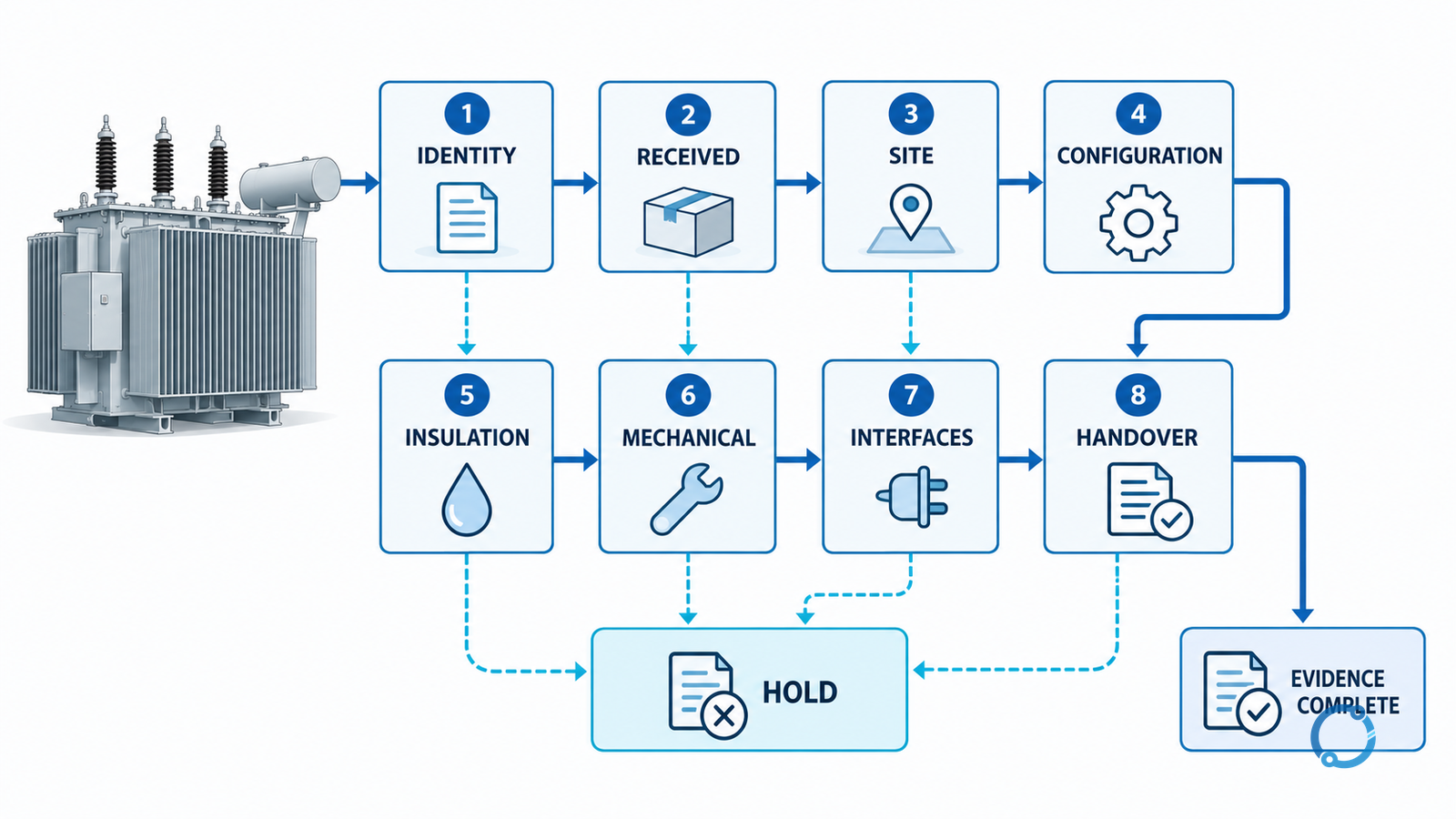
Use eight gates, not one sign-off
A single “installation complete” tick is too coarse. It allows a correct nameplate to hide a missing anchor, or a clean test sheet to hide an unresolved shipping inspection. Split the journey into eight gates that can each be released, held or rejected.
| Readiness gate | Evidence that closes it | Hold it when |
|---|---|---|
| 1. Identity and scope | Purchase order, unit tag, nameplate, serial number, approved schedule and accessory list agree | Any identifier, rating, configuration or scope item is unexplained |
| 2. Received condition | Shipping inspection, packaging evidence, impact indicators, photographs, accessory inventory and damage disposition | Damage, moisture ingress, missing parts or an unresolved transport claim remains |
| 3. Site and access | Approved foundation, support, anchorage, drainage, fire and environmental provisions, lifting route and working access are complete | Civil work, access, drainage or environmental control is incomplete |
| 4. Configuration | Nameplate and approved drawings agree on voltages, frequency, phases, vector group, taps, cooling and specified accessories | A design change has no approved change record |
| 5. Insulation and liquid state | Applicable electrical and fluid checks follow an approved plan with valid conditions and records | Instrument, temperature, method, fluid data or prior evidence is unsuitable |
| 6. Mechanical and environmental interfaces | Enclosure, bushings, seals, valves, radiators, ventilation, heaters and accessory supplies are correct and intact | A leak, obstruction, damaged interface or unsupported installation condition remains |
| 7. Electrical interfaces | Terminals, phase identification, earthing and bonding, CT/VT circuits, control power, protection trips and interlocks match the approved design | A connection, polarity, label, torque record or functional result is unverified |
| 8. Handover evidence | As-left drawings, test records, deficiency register, isolation state and completion approvals are assembled | The next team cannot tell what was installed, tested or left isolated |
The gate sequence is a release model, not a universal construction method. The responsible engineer can combine checks when the approved procedure allows, but cannot treat an unanswered gate as complete.
Start with authority, isolation and the unit’s boundary
Before anyone opens a panel, removes transport protection or tests a winding, identify the equipment boundary. Mark which cables, busbars, control supplies, auxiliary supplies, capacitors, generators, uninterruptible supplies and communication paths can reach the transformer. Include sources that are electrically separated on the drawing but could still be coupled inductively or through control circuits.
For covered general-industry work in the United States, the Occupational Safety and Health Administration’s electrical work-practices rule, 29 CFR 1910.333, requires exposed equipment to be de-energized unless the stated exceptions apply. It also says that a circuit which has been switched off but has not been locked or tagged is treated as energized. The separate hazardous-energy rule, 29 CFR 1910.147, establishes a lockout/tagout framework where its scope applies. Other jurisdictions and facilities use different text and procedures, but the practical question is the same: who controls every source, and how is control verified?
Record:
- the equipment identifier and electrical boundary;
- every normal, alternate, control and stored-energy source;
- the device used to isolate each source;
- the locks, tags, blocks or other controls applied;
- who verified the isolation and when;
- what work remains outside the permitted scope;
- what state the equipment must be left in at the end of the task.
Stored energy deserves its own line. Capacitors, charged control circuits, springs, compressed-gas or hydraulic actuators, suspended loads and rotating equipment can move or re-energize parts after the main supply disappears. The required discharge, blocking and verification method belongs to the approved equipment procedure. “Switched off” is not the same as “controlled.”
Receive and identify the transformer
The safest time to capture receiving evidence is before the unit is unpacked, lifted or moved into a position where some signs of impact become impossible to see. A receiving inspection should involve the people who can stop a damaged delivery, not only someone signing for the crate.
Match the unit and its accessories against the approved procurement record:
- project equipment tag and purchase-order item;
- manufacturer’s nameplate and serial number;
- rated power, voltages, frequency, phases and current basis;
- vector group or winding connection as stated on the approved schedule;
- tapping range, impedance and cooling designation where specified;
- transformer type, fluid or insulation system and environmental class where applicable;
- bushings, cable boxes, surge arresters, fans, pumps, gauges, sensors, thermometers, heaters, valves and other specified accessories;
- shipping sections, loose parts, keys, tools, test certificates and instruction documents.
Do not use “the nameplate has a similar rating” as evidence that the right configuration arrived. The full arrangement must agree with the approved design and the contract. The IEC 60076 transformer specification guide explains why a short standard reference is not a complete equipment specification. Its contract checklist is useful here because receiving is where those promised fields become visible facts.
Inspect packaging, impact indicators, braces, jacking marks and protective covers without defeating the manufacturer’s protection. Take photographs that show the equipment tag, damage location and relevant indication in one credible view. If a leak, cracked bushing, displaced barrier, broken seal or missing accessory is found, isolate the affected item and quarantine it for the responsible authority. Do not tighten, bend, fill, top up or hide a defect merely to complete the receiving checklist.
The receiving record should end in one of three states: released for movement or installation, released with a controlled exception, or held. “Verbal acceptance” is not a state that the next shift can audit.
Prove that the site is ready for this transformer
Foundation and access checks must reflect the actual unit, not a previous project. Review the approved civil and structural package against the delivered equipment and the planned installation method. The competent team should confirm the load path, supporting surface, anchor positions, embedded items, drainage, containment, fire separation, ventilation, cable or busbar routes, control-cable entries and the working space required for installation and later inspection.
Keep these checks within their evidence boundary. A photograph of a clean concrete plinth does not prove that it has the required strength or elevation. A drawing that shows a fence does not prove that it is installed, lockable and suitable for the site’s access procedure. A floor drain does not prove that liquids cannot reach a prohibited path. The responsible civil, structural and electrical reviewers determine what must be measured, inspected or certified.
Plan the movement before moving the unit:
- verify the approved lifting or jacking points and the competent person’s method;
- confirm that the route can carry the transport load and has the required turning clearance;
- protect bushings, fans, radiators, controls and enclosure projections from damage;
- control exclusion zones around suspended loads and moving equipment;
- verify that temporary supports, skates or rails cannot introduce a hazard;
- leave access for the final connection, earthing inspection and future maintenance;
- do not use a support, jack, lifting point or temporary restraint that is not approved for the unit and method.
The transformer’s own operating and environmental requirements are part of site readiness. Liquid-immersed and dry-type transformers have different ventilation, containment, fire and access considerations. Enclosure or environmental class may impose conditions that cannot be assessed from a generic checklist. Compare the approved transformer type and service conditions with the actual site rather than fitting the site to an assumed transformer.
Record a hold when the foundation, route, enclosure or environmental arrangement is incomplete. Moving the unit into an unfinished area can turn a civil defect into a handling and rework problem.
Reconcile the configuration against the design
The installation team needs a clean answer to this question: is this the transformer the electrical system is expecting? That requires more than matching the power rating.
Build a field-to-design comparison for the configuration fields that affect connection and testing:
| Field | Where it must appear | What to confirm |
|---|---|---|
| Equipment identity | Tag, purchase order, nameplate, serial number | The physical unit and all records describe the same item |
| Voltage and frequency | Nameplate and approved schedule | Primary, secondary, turns ratio, phase relation and frequency agree |
| Phase and vector relationship | Nameplate, schedule and connection drawing | The winding arrangement and external connections are unambiguous |
| Tap range | Nameplate and approved tap schedule | Available taps and required initial position are recorded |
| Impedance and current basis | Nameplate or test document, approved schedule | Ratings and future protection studies use the correct basis |
| Cooling and thermal state | Nameplate, cooling diagram and accessory list | Fans, pumps, sensors and control logic match the specified configuration |
| Environmental features | Nameplate, enclosure drawing and site assessment | Indoor or outdoor use, ventilation, ingress protection and atmosphere are consistent |
| Accessory set | Approved bill of materials and as-supplied inventory | No specified instrument, heater, control or protective device is missing |
A rated quantity that is correct on its own can still belong to the wrong system when read with the other fields. The OHELE kVA rating-basis guide explains why rated power is not a stand-alone statement. Use that logic when reconciling receiving evidence with the design.
If the nameplate, drawings or supplier documents disagree, do not allow a quick field change to resolve the conflict. Raise a formal question, obtain the approved correction and update every affected record before connection. Unapproved changes to voltage links, tap position, CT ratio, control logic or protective settings can make later tests prove the wrong arrangement.
Inspect the enclosure and accessory state without inventing values
The installation inspection should look for conditions that would make the approved procedure unsafe or unverifiable. Check the condition and completeness of:
- tank, enclosure, base and support interface;
- bushings, insulators, barriers and terminal covers;
- gaskets, seals, pressure devices and fluid sight or level indicators where fitted;
- valves, breathers, radiators, fans, pumps and pipework where specified;
- lifting points, transport braces and temporary restraints;
- heaters, thermometers, temperature sensors, current transformers and accessory wiring;
- ventilation openings, filters, drain paths and enclosure doors;
- labels, phase markings, hazard signs and identification plates;
- control and auxiliary power supplies and their isolation points.
Transport braces often need to be removed before operation, but the instruction may specify when and in what order. Do not remove a restraint because it looks temporary, and do not leave one installed because removal requires an approved tool or method. The same discipline applies to protective shipping covers or desiccant packs: the equipment instructions determine what remains until a fluid test, pressure check or inspection releases the next stage.
Leaks, loose accessories, unusual pressure, displaced seals, damaged ventilation or a missing protection device are hold conditions until assessed. Some checks require opening a guarded compartment or working near stored energy; those belong to a qualified person operating under the approved isolation procedure. A visual inspection from outside the boundary may be all the installation team is authorized to do.
Establish insulation and liquid readiness on a controlled basis
Insulation and fluid checks connect the received unit to the state intended for service. The correct evidence depends on transformer type and design:
- a dry-type transformer may require cleanliness, mechanical condition, winding condition and insulation measurements;
- a liquid-immersed transformer may require level, leak, pressure or sealing evidence, fluid records and an appropriate dielectric assessment;
- sealed, gas-filled or special transformer designs may require additional checks or a different procedure entirely.
Do not use one generic pass/fail value across those cases. An insulation-resistance result depends on the instrument, test voltage, temperature, humidity, winding configuration, leakage paths, prior history and the approved method. The OHELE guide to insulation-resistance testing describes the variables and why a single reading needs a controlled baseline. On a transformer, the test plan must also address what is disconnected, where the measuring leads are applied, how stored energy is controlled and what result is comparable with prior evidence.
Record the test context before interpreting the result:
- identify the winding and terminals involved;
- record wet-bulb and ambient temperature or the specified correction basis;
- identify the test instrument and approved test range;
- record insulation and grounding conditions;
- retain the actual result and the unit or scale;
- state whether the reading is compared with a prior result, a batch requirement or a project acceptance basis;
- have the authorized person interpret any trend or abnormal result;
- re-establish protective earths and covers after the test.
The test result must not be separated from the equipment state. The transformer should have no cable or structural connection that could create an unintended path. Accessories that are sensitive to test voltage, such as some electronic devices, may need to be disconnected or protected, while current transformers and other circuits may present their own risks. Follow the approved plan; do not discover the connection method by looking at one instrument and one winding.
A liquid or gas result also needs context. A sample label must identify the transformer, sampling point, date, method and seal. A laboratory report needs the correct fluid type, test method and limits from the approved specification. An old report from a similar unit is not evidence for this unit. A low level is not corrected by adding fluid until the loss path and the required fluid are understood.
Where the approved procedure requires testing that the installation team is not authorized to perform, keep the gate open. “Test later” is acceptable only when the handover clearly states that the equipment is not released for the next stage.
Close the mechanical, earthing and connection interfaces
The installation team’s most visible work is the transition from a delivered unit to a connected system. The most important record is less visible: every interface has a known design, a known installed state and an approved verification result.
Terminals and conductor supports
Identify the terminal design and approved hardware. Verify that the conductor, cable lug, busbar, adapter or plug-in connection is suitable for the terminal and the intended current. Confirm the conductor route provides the planned strain relief and does not transfer unsupported load to a bushing or terminal block. Record the approved tightening method and value where the equipment documentation specifies one; do not substitute a familiar torque from another product or a remembered value.
Check phase identification against the approved drawing. Phase order, winding polarity and terminal designation can affect protection, direction of rotation and the vector relationship. A visually neat connection is not a verified connection.
Earthing and bonding
Confirm that the transformer’s exposed conductive parts and specified system points are bonded to the designed earthing path. Identify the connection points, conductor and hardware, then verify continuity and secure attachment as required by the approved inspection plan. The OHELE main bonding sizing checks explain why a visible green-and-yellow conductor is not enough evidence of the correct protective path.
Do not use a temporary earth or test lead as part of the permanent installation unless the design and procedure require it. Remove temporary earths under the responsible person’s control before the equipment state changes, and record that removal.
Instrument transformers and protection
Where current transformers (CTs) are part of the transformer connection, verify ratio, polarity, core assignment and secondary circuit routing against the protection and metering schedule. The OHELE current-transformer installation and testing workflow covers the dedicated checks and safe handling boundary. Never open a CT secondary circuit while current is flowing; the correct procedure must be established before any connection or test.
Verify the trip and alarm paths from the transformer’s specified devices to the approved protection or control system. Confirm temperature trips, pressure or fluid devices, fan controls, door or breaker interlocks, auxiliary contact status and supervisory alarms where applicable. A control terminal with the correct label does not prove that the signal reaches a trip or alarm. Use the approved point-to-point and functional test method, with test energy controlled and any temporary test settings restored afterwards.
The transformer differential relay settings workflow is a separate calculation task, but the installation record should identify whether the CT circuits, relay inputs and protection group match the approved setting file. Do not leave a relay in a temporary test state, with forced values or a bypassed trip, without a visible control and an approved restoration step.
Auxiliary supply and environmental controls
Record the supply, overcurrent protection and isolation point for heaters, fans, pumps, valves, gauges and control equipment. Where required, verify the direction of rotation before coupling to a process, and confirm that a heater is controlled so it does not operate in the wrong state for the equipment. Inspect filters, ventilation paths and drain openings. Commissioning a fan by hearing it run does not prove that airflow is unobstructed or that the intended alarm works.
Turn the field state into a handover record
Installation is ready to hand over when the next competent team can understand the equipment without relying on a conversation. A useful handover package contains:
- the approved equipment and connection drawings with the as-left field version;
- receiving records, damage dispositions and missing-item closure;
- the approved foundation, support and access acceptance evidence;
- nameplate and design reconciliation;
- insulation, fluid or gas records and the limitations of those records;
- torque, continuity, phase and functional test records;
- protection, control, alarm and interlock results;
- temporary earths, test links, forced points and test settings removed or still controlled;
- the exact isolation state of every remaining energy source;
- an open-item register that names each hold, its owner and the evidence still required;
- a completed release statement that identifies the next stage and who may authorize it.
The MV switchgear commissioning release guide uses the same principle at the assembly boundary: evidence must support a release, not simply accompany the equipment. For a transformer, that boundary must also connect back to the civil, protection and cable or busbar teams.
Stop when one gate is unresolved
An unresolved gate is not a communication problem to be hidden in a long punch list. It is a reason to stop the next stage when that stage could make the equipment unsafe, damage evidence or create a false sense of completion. Consider a hold when:
- the delivered rating, vector group, tap range, cooling arrangement or accessory set differs from the approved design;
- shipping damage, a fluid loss, unusual pressure or moisture evidence has not been assessed;
- the foundation, anchorage, lifting route, access or containment is incomplete;
- an enclosure or environmental condition differs materially from the design basis;
- an insulation or fluid result is abnormal, non-comparable or was taken under uncontrolled conditions;
- a terminal, barrier, earthing connection, CT/VT circuit or control path is unverified;
- a temporary test link, forced signal, isolation or protective action remains in an unknown state;
- a protection or control test has been passed only by bypassing the actual trip path;
- the next team cannot identify what is isolated and who may change that state.
Closing a hold requires the evidence that failed, not a more confident signature. If a test was performed at the wrong temperature, repeat it under the approved method. If a connection was tightened using an unapproved value, review the connection and obtain the correct acceptance evidence. If a cable or control change altered the design, update the drawings and affected protection records before handover.
Keep installation release separate from energization
The end state of this guide is an equipment installation record that is complete enough for a separate commissioning or energization review. It is not:
- approval to close the supply breaker;
- proof that the transformer is healthy under all operating conditions;
- a substitute for the transformer protection study;
- a guarantee that the phase relationships at the remote ends are correct;
- a test of the transformer’s ability to carry load or withstand a fault.
Before energization, the responsible team must confirm the switching authority, protection status, tap position, earthing state, cooling controls, communication method, emergency stop or trip path and the response to an abnormal sound, pressure or alarm. Those steps depend on the equipment, system and local procedure and belong in the approved energization plan.
The installation release is still valuable. It gives the energization team a clean starting state: the right unit in the right place, with known condition and configuration, verified interfaces and every unresolved question visible by name.
Sources
- IEC 60076-1:2011 — Power transformers, general
- 29 CFR 1910.333 — Selection and use of work practices
- 29 CFR 1910.147 — Control of hazardous energy
The IEC catalogue page was checked for the standard’s public scope on 2026-10-24; the full standard is paywalled and was not accessed. The OSHA citations describe U.S. general-industry requirements and do not replace the locally adopted code, utility rules or an approved transformer and site procedure. Exact acceptance values, test methods and energization steps must come from the project design, equipment instructions and the responsible electrical authority.