
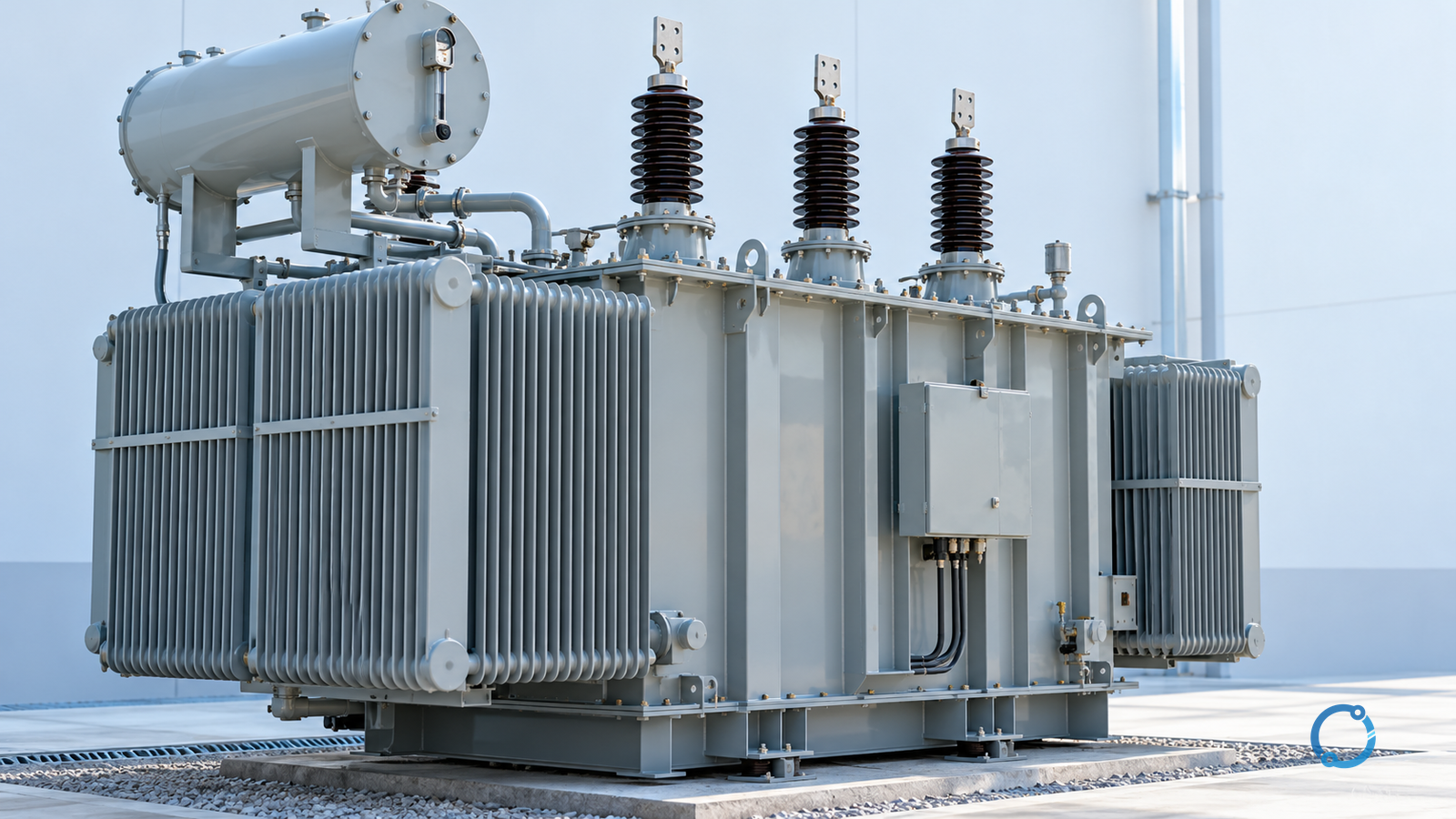
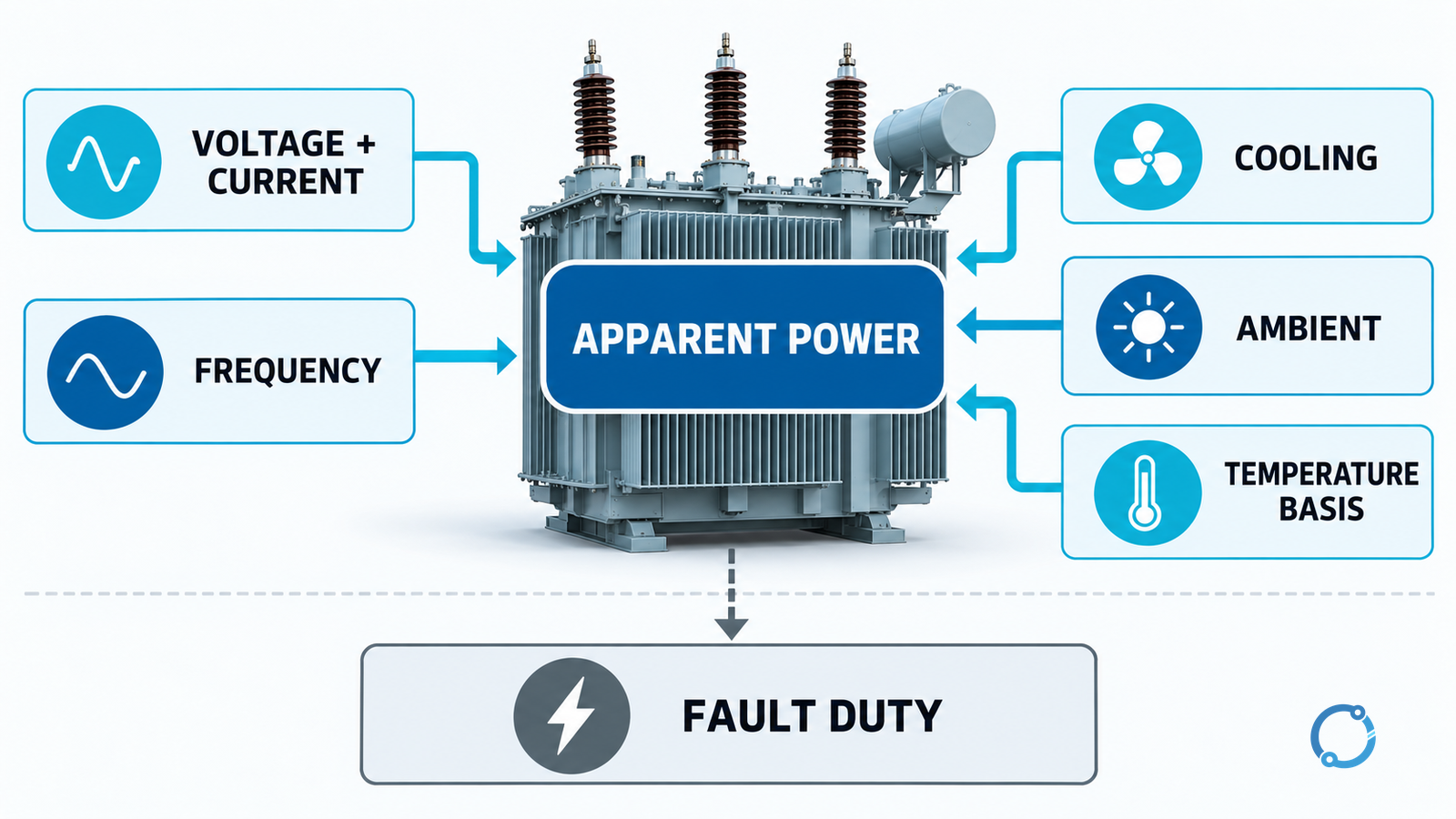
A transformer’s kVA or MVA rating is an apparent-power capability under declared voltage, frequency, cooling and temperature conditions. It is not a measured kW output and it is not a promise that the transformer can carry the same current in any enclosure, ambient temperature or load cycle.
The nameplate condenses several distinct facts: winding voltage and current, frequency, rated power, cooling stage and temperature-rise basis. Those facts must stay together. A 1,000 kVA label by itself does not tell you whether the unit is naturally cooled, fan-assisted, suitable for the site’s ambient temperature, able to withstand the available fault current or acceptable for a particular load.
The rating answers a thermal question
Current in transformer windings produces copper loss. Alternating flux in the core produces no-load loss. Those losses heat the core, windings, insulation and surrounding structure. The transformer’s thermal design must dissipate that heat while keeping temperatures within the insulation and equipment limits assumed for its rating.
That is why apparent power is useful to the rating: voltage sets the insulation and flux stress, while current sets the winding heating. Under a sinusoidal load:
S = V x I
for a simple single-phase quantity, and for a balanced three-phase system:
S = sqrt(3) x VLL x IL
with VLL in volts, IL in amperes and S in volt-amperes. Divide by 1,000 for kVA. The rating is declared for stated service conditions, not derived from one current measurement alone.
The IEC 60076-1:2011 catalog identifies the general power-transformer scope, including ratings and service conditions. The official catalog identifies responsibilities; it does not certify a particular unit or grant access to the full technical clauses.
Read the rating as a bundle of conditions
A defensible rating comparison records:
| Input | Why it belongs beside the kVA value |
|---|---|
| Rated power and number of phases | Establishes total apparent power, not per-phase power |
| Winding voltages and frequency | Defines the voltage and current basis and insulation duty |
| Winding connection and neutral arrangement | Changes line/winding relationships and fault paths |
| Cooling method and stage | Identifies whether a rating depends on fans, pumps or another cooling state |
| Temperature-rise basis and ambient conditions | Makes the thermal claim comparable with the installation |
| Impedance and short-circuit withstand | Separates normal-duty thermal capacity from fault duty |
| Tap range and operating voltage | Changes current and flux conditions at the service tap |
| Loss, sound and auxiliary conditions | Completes performance and operating comparisons |
The critical point is not to memorize a universal checklist. It is to refuse a kVA comparison when the two ratings were established on different cooling or temperature bases.
Cooling stages can carry different ratings
A transformer may have more than one declared cooling state. A naturally cooled state might support one rating while forced cooling supports a higher one. Those are not two equally available ratings under every condition: the higher value depends on the fans or pumps operating, on auxiliary power and on the thermal assumptions in the design.
Do not select a higher rating just because the fan curves show that state. Ask:
- which state is the normal operating state for the project;
- what load is permitted if a fan or pump becomes unavailable;
- how the loss of auxiliary cooling is detected and controlled;
- what time and temperature limits apply to a transition;
- whether the site has the auxiliary power and maintenance capability needed.
The IEC 60076-2:2011 catalog identifies the temperature-rise relationship for liquid-immersed transformers; the IEC 60076-7:2018 catalog addresses loading and thermal ageing for mineral-oil-immersed transformers. Their public scopes support the questions here, but the actual edition and design data govern the unit.
kVA, kW and power factor are not interchangeable
For sinusoidal conditions, real power is:
P = S x cos(phi)
where cos(phi) is the displacement power factor. A transformer rated at 1,000 kVA supplies 900 kW when the load displacement factor is 0.90:
1,000 kVA x 0.90 = 900 kW
That does not mean 1,000 kVA is an entitlement to 900 kW under every power quality condition. Harmonics, unbalance, voltage variation and losses can change the current required for the same useful output. The transformer supplies apparent power; the load’s real and reactive components determine what the facility can use.
Here is a useful reverse check. If a proposed load is 900 kW at a displacement factor of 0.90, its sinusoidal apparent-power demand is:
900 / 0.90 = 1,000 kVA
If the power factor rises to 0.95 at the same real power, the apparent-power demand falls to approximately 947.37 kVA. This arithmetic shows why a power-factor correction study can affect capacity planning, but it does not grant permission to exceed the transformer’s thermal limits.
Convert the rating into current with the right voltage
For a balanced three-phase transformer rated 1,000 kVA at 400 V line-to-line, the rated line current is:
IL = 1,000,000 / (sqrt(3) x 400) = 1,443.38 A, approximately.
That current is a calculated line current at the declared rating and voltage. It does not tell you the safe loading of a particular feeder, the rating of a switchboard, or the available fault current. The conductor and protection design must use the actual voltage, connection, harmonics and operating states.
The Wye transformer calculation guide keeps line and winding quantities separate. Use it when the winding basis matters; do not apply a line-current value directly to every winding.
Why impedance is a separate rating conversation
Impedance controls the transformer’s contribution to fault current and affects voltage regulation and parallel operation. A transformer can have a normal continuous kVA rating that looks adequate while its impedance and the connected system produce a fault duty beyond a downstream breaker or assembly rating.
That is why a kVA comparison must be followed by a short-circuit study. For low-voltage assemblies, IEC 61439-1:2020 sets the general assembly framework used with the applicable product part. A transformer’s own rating does not confer the assembled switchgear’s short-circuit withstand.
The same distinction applies to overload. A transformer may be thermally capable of a short, controlled overload under specified conditions, but a generic 10%, 20% or 30% margin is not a universal permission. Cooling state, starting temperature, duration, ambient and insulation ageing must be assessed for the actual design and load cycle.
A rating plate is evidence, not a complete selection
Record the nameplate and the project conditions together. The equipment may show:
- rated power and voltages;
- rated currents and frequency;
- connection and tap data;
- cooling-stage designations;
- temperature-rise and ambient basis;
- impedance and loss information;
- serial and asset identifiers.
Do not infer that the transformer will serve a proposed load just because the apparent-power total is below the plate value. Check the load profile, power factor, harmonics, starting events, neutral and earth-fault path, short-circuit duty, voltage regulation, environmental conditions and the assembly around it.
The IEC 60076 transformer specification checklist turns these inputs into a purchasing schedule. For the next step, use the transformer kVA selection workflow to compare candidate sizes against load duty. The rated plate and the calculated demand answer different questions.
Bottom line
Transformer rating is based on apparent power and a defined set of service and thermal conditions. Read kVA with voltage, frequency, cooling, ambient and temperature-rise basis; calculate real power with power factor; and verify impedance, fault duty and load profile separately. When any of those conditions is missing, call the number provisional.