
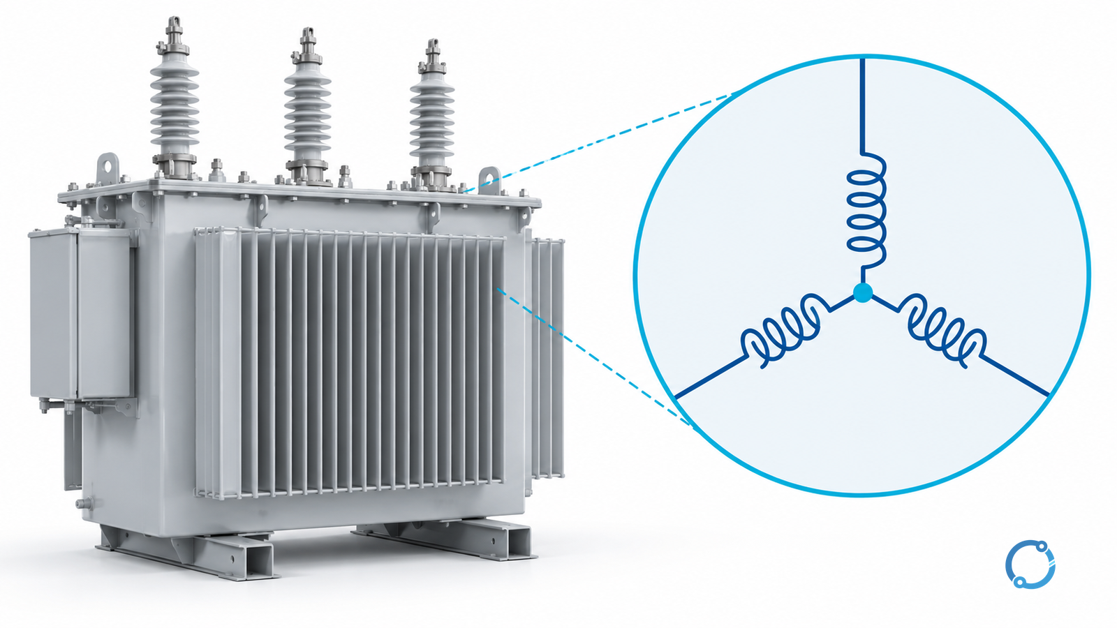
For a balanced wye-connected transformer winding, line current equals winding current, while line-to-line voltage equals sqrt(3) times winding voltage. In this article, winding voltage means the line-to-neutral voltage developed across one phase winding. Total apparent power is:
S = sqrt(3) x VLL x IL = 3 x Vw x Iw
Those equations apply to balanced steady-state root-mean-square (RMS) magnitudes under the ideal model stated below. They do not authorize reconnecting a transformer, loading its neutral, selecting protection or assuming that an accessible star point is a grounding electrode. Keep the transformer side, line or winding basis, and unit attached to every number.
Put line and winding values on separate rows
Use these symbols consistently:
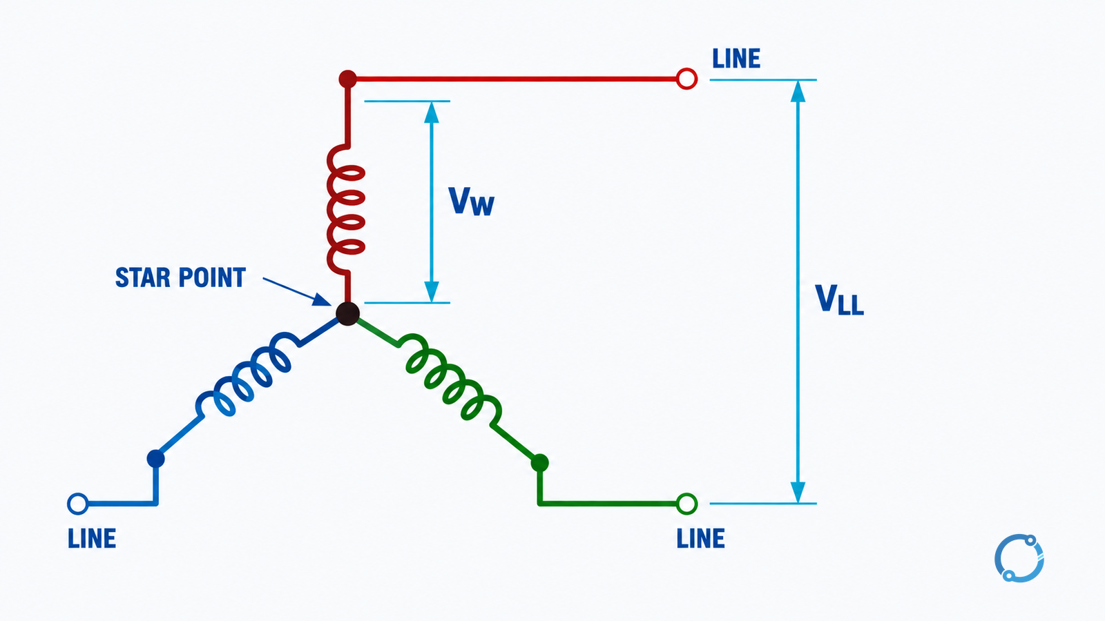
- VLL is the RMS voltage between two external line conductors;
- Vw is the RMS voltage across one wye winding, commonly line-to-neutral;
- IL is the RMS current in an external line;
- Iw is the RMS current through one phase winding;
- S is total three-phase apparent power;
- subscripts 1 and 2 identify primary and secondary.
| Quantity | Wye winding | Delta winding, for comparison |
|---|---|---|
| Winding voltage | Vw = VLL / sqrt(3) | Vw = VLL |
| Winding current | Iw = IL | Iw = IL / sqrt(3) |
| Total apparent power | S = sqrt(3) x VLL x IL = 3 x Vw x Iw | Same total-power expressions under the balanced model |
| Corresponding winding ratio | a = Vw1 / Vw2 | a = Vw1 / Vw2 |
The US Department of Energy’s Electrical Science handbook, Volume 3, module ES-09, gives the balanced wye and delta relationships. Volume 4, module ES-13, explains transformer turns ratio. These are historical fundamentals references, not newly issued standards.
The visual map below keeps external line values outside the wye and winding values on the branches. The external conductors and the star point must not be treated as interchangeable terminals.
Worked example: 300 kVA wye secondary
Assume a hypothetical ideal transformer with a 300 kVA balanced rating, an 11 kV delta primary and a 400 V line-to-line wye secondary. Ignore losses, exciting current, regulation, harmonics and unbalance. The values are a teaching example, not a product nameplate.
First calculate the primary and secondary line currents from the same total apparent power:
IL = S / (sqrt(3) x VLL)
- Primary line current: 300,000 / (sqrt(3) x 11,000) = 15.75 A, approximately.
- Secondary line current: 300,000 / (sqrt(3) x 400) = 433.01 A, approximately.
Because the secondary is wye connected, its winding current is also 433.01 A approximately. Its winding voltage is:
Vw2 = 400 / sqrt(3) = 230.94 V, approximately.
Check the power from the secondary winding values:
3 x 230.94 x 433.01 = 300,000 VA, within rounding.
Do not multiply the 300 kVA total by three again. The rating already represents all three phases.
Calculate the winding ratio, not an assumed line ratio
For the wye secondary above, each secondary winding has approximately 230.94 V. Its corresponding ideal winding turns ratio to the 11 kV primary delta winding is:
a = 11,000 / 230.94 = 47.63, approximately.
That is different from the external line-voltage ratio:
11,000 / 400 = 27.5
Both numbers can be correct for different quantities. A transformer’s vector group, polarity, phase displacement and terminal arrangement determine how the winding ratio appears at the external terminals; the basic magnitude calculation does not supply a vector group.
This distinction also explains why replacing “delta” with “wye” changes the line-voltage relationship without changing the winding design. It does not mean that a field reconnection is acceptable. Winding insulation, terminal accessibility, neutral construction, rated voltage, vector group and the equipment instructions all control that decision.
Wye does not automatically mean a grounded neutral
A three-phase wye winding has a star point by construction, but the existence of that point does not prove:
- that the neutral is brought out to an accessible terminal;
- that it is designed to carry load or harmonic current;
- that it is solidly grounded, impedance-grounded or left isolated;
- that the source grounding arrangement matches the installation;
- that a line-to-neutral load can be added.
Those are system and equipment design decisions. The neutral’s insulation, current duty and connection must be stated in the transformer specification and confirmed on the approved drawings. Neutral arrangement affects fault paths and protection; it is not a cosmetic calculation detail.
For the broader system decision, read OHELE’s neutral earthing system selection guide. It addresses fault current, continuity and protection rather than the voltage ratio alone.
Why balanced equations stop short of an unbalanced load
The sqrt(3) relationship assumes equal winding voltages and a balanced, sinusoidal set. Suppose single-phase loads are connected from different lines to the neutral. Their current magnitudes, phase angles and switching times can produce a neutral current and unequal winding currents. A simple “line current equals winding current” statement remains true at each individual wye branch connection, but the balanced set of load currents no longer describes the operating state.
The same warning applies to harmonics and transformer connections. Zero-sequence current paths depend on the winding connection and grounding, and triplen harmonics can behave differently from the positive-sequence fundamental. Use a study that represents the actual load spectrum and transformer zero-sequence path; do not apply the balanced kVA equation to every nonlinear or single-phase load.
Five checks before releasing a wye calculation
- Label the side and basis. Write “primary winding voltage,” “secondary line current,” or “total apparent power” rather than an unlabeled voltage or current.
- Use rated three-phase power once. Do not treat 300 kVA as 900 kVA by multiplying across three phases a second time.
- Match the ratio to the quantities compared. Apply the winding ratio to corresponding winding quantities; use the actual connection when external line values are involved.
- Separate star point, neutral and earth. Confirm the specified connection rather than inferring electrical function from a schematic symbol.
- Reject the balanced result when its assumptions fail. Severe unbalance, harmonics, fault current, saturation or transient conditions need a different model.
For a delta-connected winding, keep line and winding quantities on separate rows using the comparison in the table above. For a complete transformer specification beyond these calculations, see the IEC 60076 purchaser’s checklist. A valid arithmetic result does not establish thermal capacity, insulation suitability, fault withstand or compliance.