
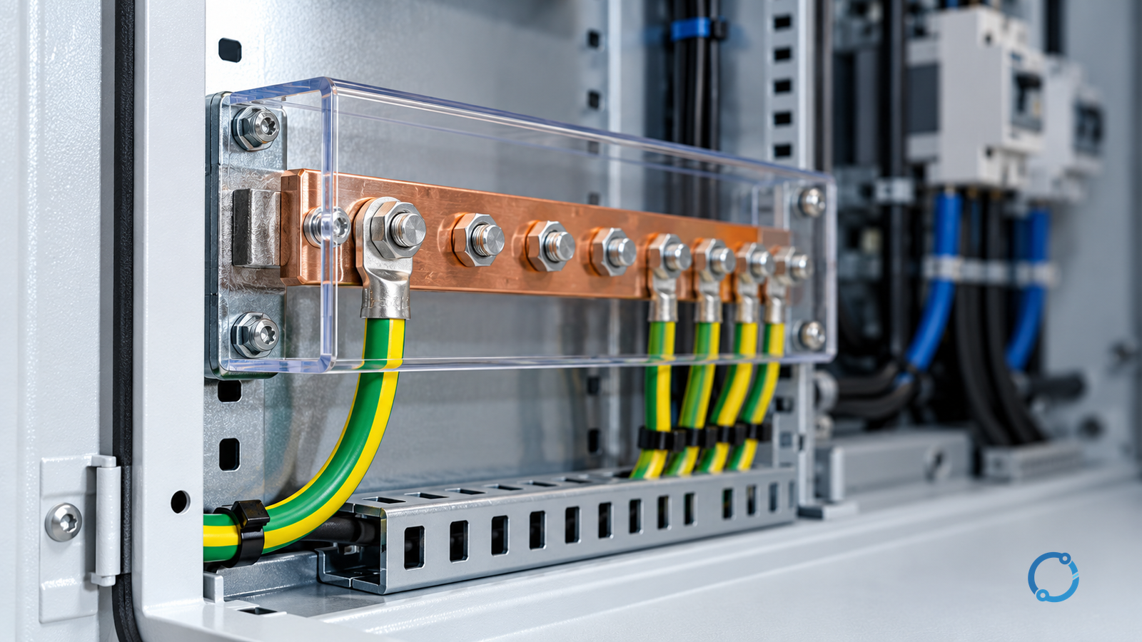
Equipment grounding conductor sizing in the United States is a code-verification task, not a generic wire chart lookup. First identify the conductor’s role and the exact circuit. Then use the locally adopted edition of NFPA 70, the National Electrical Code, including amendments and the authority having jurisdiction’s interpretations. Section 250.122 provides the minimum sizing rule for a wire-type equipment grounding conductor based on the overcurrent protective device, and the same article contains requirements for increases, permitted methods and related conditions.
The current NFPA catalogue identifies the 2026 edition, but adoption changes by jurisdiction and date. A design that cites a national edition without checking the adopted local code is not a complete verification. This article therefore does not reproduce Table 250.122 or convert it into an unofficial replacement table. Use a current licensed copy of the adopted code and the project’s approved design documents.
Equipment grounding conductor work is part of the overall fault path and life-safety system. It must be installed and verified by qualified persons under the applicable permitting, inspection and employer safety procedures. OSHA 29 CFR 1910.304 provides separate U.S. general-industry installation requirements. The article does not replace the code, local amendments, the AHJ or a licensed electrical design.
The first step is to identify what the conductor is doing
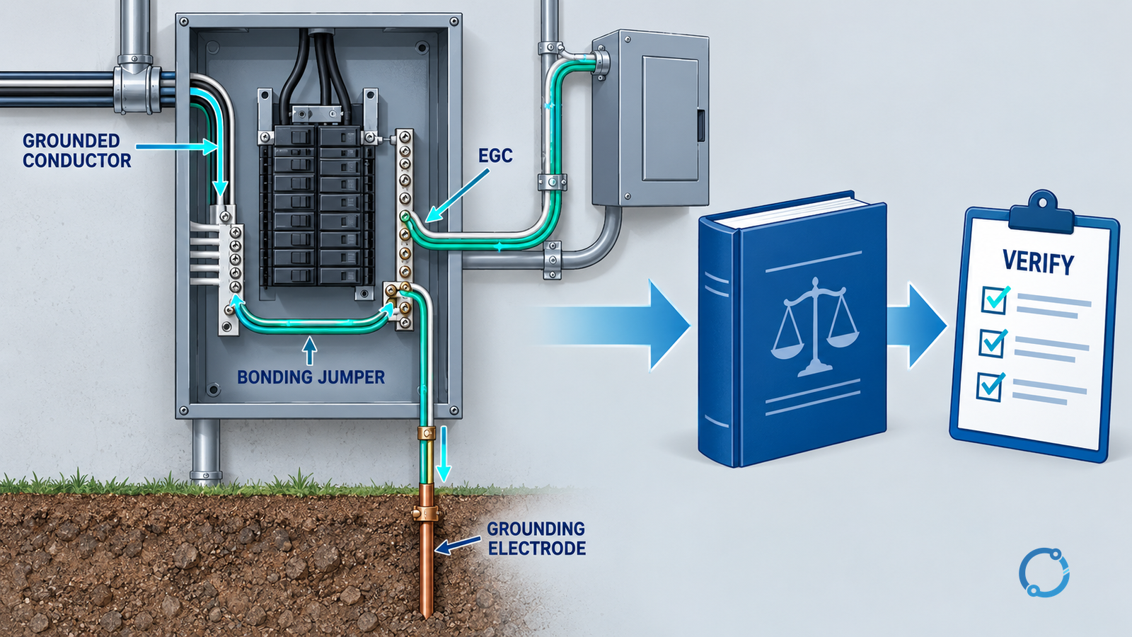
Grounding and bonding language is easy to mix because several conductors are green, bare or connected to earth-like paths. The sizing rule depends on the role:
| Conductor or connection | Primary function | Why it is not interchangeable with an EGC |
|---|---|---|
| Equipment grounding conductor | Provides an effective ground-fault current path for normally non-current-carrying metal parts | Its sizing follows the circuit protective device and Article 250 requirements |
| Grounded conductor | A circuit conductor that is intentionally grounded | It carries normal operating current and has separate sizing and identification rules |
| Grounding electrode conductor | Connects a grounding electrode system to the grounded system or equipment | It serves a different system-grounding function |
| Bonding jumper | Electrically joins metal parts to establish continuity | The required size and location depend on the specific bonding function |
| Supply-side bonding jumper | Bonds metal parts on the supply side within the specified scope | It is not a substitute for the circuit EGC |
| Equipment bonding jumper | Maintains the fault path across a removable or separated equipment connection | Its sizing and installation conditions come from the applicable Article 250 rules |
A conductor cannot be called an EGC merely because it is green or because it eventually reaches earth. Start with the fault-current path and the code definition. Then identify the circuit conductors, protective device and source configuration.
Establish the governing code edition
Record:
- project state, city or other adopting jurisdiction;
- adopted NEC edition and effective date;
- local amendments or replacements;
- project specification and approved drawings;
- authority having jurisdiction’s written interpretation where a question remains;
- edition used by the electrical contractor and inspection record.
Do not combine a 2026 table title with a 2020 local adoption. Do not assume that a change in the national model code applies where the local authority still enforces an earlier edition. The code citation in a calculation should identify edition and article or section, not just “NEC.”
Map the circuit before selecting a size
Create a one-line or circuit record containing:
- source and service or separately derived system;
- feeder or branch-circuit identifier;
- phase, neutral and equipment grounding roles;
- overcurrent protective device type and rating;
- conductor material, size, insulation and installation method;
- number of conductors and whether any are increased for voltage drop, temperature, derating or future capacity;
- raceway, cable, tray or other permitted EGC method;
- load characteristics and expected fault path;
- coordinates of the upstream and downstream connection points.
The “rating” of the overcurrent protective device is an input to the EGC rule, but it is not the only number on a breaker label. Identify the correct device characteristic and the exact circuit being protected. A main breaker, feeder breaker, motor branch protection device and supplementary protector may not play the same role under Article 250. Consult the adopted code and approved design.
Circuit identification also prevents a dangerous substitution: a neutral with a larger ampacity is not an EGC, and a grounding electrode conductor installed for a service is not automatically the correct EGC for a downstream branch circuit.
Follow the Article 250 rule in the adopted code
The standard verification sequence is:
- Confirm that the circuit is within the applicable NEC and project scope.
- Identify the equipment grounding conductor and every metal part it must bond.
- Determine the governing overcurrent protective device for the circuit.
- Use the adopted edition’s Section 250.122 table or permitted method to identify the minimum wire-type EGC.
- Check whether any ungrounded circuit conductors were increased in size and apply the edition’s proportional-increase requirement, including exceptions and conditions.
- Check whether the selected EGC method is permitted for the raceway, cable, equipment and installation.
- Verify terminations, continuity, identification, routing, protection from damage and bonding around removable equipment.
- Record the result and inspect it against the approved drawings before energisation.
Do not reverse the order by choosing a familiar conductor size and searching for a rule that permits it. The overcurrent device, circuit conductors and installation method drive the answer.
Understand the proportional-increase check
Section 250.122(B) addresses the case where ungrounded circuit conductors are increased in size. In broad terms, the code requires the EGC to be increased proportionally under the conditions stated in the adopted edition. The purpose is to preserve a suitable fault-current path when the phase or ungrounded conductors are larger than the minimum needed for ampacity.
The exact method, exceptions and wording must be read in the adopted code. For example, increases made for voltage drop, derating, ambient correction or future capacity may trigger a review, but the applicable edition and project conditions determine the result. Do not assume that a direct ratio of copper areas is the complete rule or that every conductor increase automatically changes the answer in the same way.
A compact record should show:
| Input | Example record field |
|---|---|
| Ungrounded conductor basis | Original size, required size and reason for increase |
| Final ungrounded conductor | Material, size and installation condition |
| EGC basis from adopted code | Table row or permitted method plus edition |
| Increase calculation | Formula or method required by the adopted code |
| Final EGC | Size, material, path and permitted type |
| Reviewer note | Exception, AHJ interpretation or unresolved question |
If the final ungrounded conductor was increased for a reason outside the engineer’s original calculation, update the EGC review. A substitution made during installation can invalidate a previously correct sizing record.
Check the EGC method and complete fault path
The NEC permits equipment grounding conductors in several forms and installations within stated conditions. A wire-type EGC is only one possibility. Depending on the circuit and adopted edition, the fault-current path may involve metal raceway, cable armour, cable tray, busbar, equipment bonding jumpers or other permitted components.
For the selected method, verify:
- it is permitted for the specific circuit and occupancy;
- it is electrically continuous and mechanically secure;
- it is protected against damage at transitions, expansion joints, flexible connections and equipment terminations;
- it has adequate fault-current capacity for the time the protective device requires;
- bonding is maintained around removable covers, hinges, flexible conduit, reactors, transformers and separately mounted components;
- it is not interrupted by a switching device or isolated in a way that defeats the protective path;
- it does not carry normal load current except where the code and system design permit;
- it does not rely on an informal connection through bearings, sheet-metal screws or weather seals.
The EGC and the equipment bonding path are part of an overcurrent protection system. A conductor size alone does not establish that the path is continuous or that the protective device will clear a fault within the required time. The design must consider available fault current, clearing time, conductor withstand, termination capacity and equipment listing instructions.
Do not confuse the green wire with every bonding element
An inspector may find several green-and-yellow or bare conductors within one enclosure. They may include feeder EGCs, equipment bonding jumpers, grounding electrode conductors, grounding conductors for separately derived systems, or bonding for a specific enclosure. Each may follow a different rule.
Use a circuit role table and label the function in the drawing. For each conductor, record where it originates, where it terminates, what it bonds and which code rule applies. A single conductor may be part of several bonding paths, but that does not make every connected element interchangeable.
The separation is especially important around:
- service equipment and the service disconnect;
- transformers and separately derived systems;
- generators and transfer switches;
- panelboards and switchboards with neutral bars;
- motor controls and flexible connections;
- IT equipment, racks and isolated bonding systems where permitted;
- outdoor equipment and grounding electrodes.
Build a verifiable sizing record
For each circuit, create a record that can travel from design to installation and inspection:
| Field | Content |
|---|---|
| Project and jurisdiction | Address, adopted edition and local amendments |
| Circuit identifier | Source, feeder or branch, destination and drawing reference |
| Overcurrent device | Type, rating and protected circuit function |
| Ungrounded conductors | Size, material, final installation condition and reason for any increase |
| EGC selection | Size, material, code table or permitted method |
| Proportional check | Inputs, calculation and exception review |
| EGC type and route | Wire, raceway, cable, busbar or other permitted method |
| Bonding points | Equipment, removable parts, transitions and separately derived systems |
| Fault-path evidence | Continuity, termination and protection checks |
| Inspection result | Responsible person, date, amendment and outstanding item |
The record should not include a copied code table unless the project has the right to reproduce it. Reference the licensed edition and the exact section used. Store calculations and photographs outside the article package as project records.
Verification and energisation boundary
Continuity testing, polarity and absence-of-voltage checks must follow the approved isolation, lockout/tagout, test-instrument and PPE procedures. A low-resistance reading at one point does not prove that every bonding path is intact. A visual inspection does not prove that a concealed connection is continuous. A test result also does not override the code requirement for minimum size and permitted method.
Where a test result is ambiguous, stop and escalate rather than adjusting an instrument to obtain a desired reading. Record the test method, instrument identity, calibration status, circuit state and environmental conditions. Use a competent person to interpret results that may involve a faulty grounded conductor, a parallel path, an unintended neutral bond or a damaged raceway connection.
Eight checks before release
1. Adopted edition confirmed
The jurisdiction, effective edition and amendments are recorded. The project is not relying on a disconnected national summary.
2. Conductor role verified
The EGC is distinguished from a grounded conductor, grounding electrode conductor and bonding jumper.
3. Overcurrent device identified
The correct device and circuit are tied to the sizing table or permitted method in the adopted code.
4. Conductor increase checked
The final installed ungrounded conductors have been compared with the design basis and the Section 250.122(B) review.
5. Installation method permitted
The selected wire, raceway, cable or other path is allowed for the circuit and equipment condition.
6. Fault path continuous
Terminations, transitions, flexible sections, enclosures and removable parts preserve the intended bonding path.
7. Termination and withstand evidence recorded
The conductor and connection are suitable for the equipment and fault duty within the project design.
8. Inspection and authority review complete
The drawing, calculation, installation record and AHJ or inspection requirements are aligned before energisation.
Common mistakes
Sizing the EGC from the neutral. A neutral carries operating current and has different identification, isolation and sizing rules.
Using the service grounding electrode conductor everywhere. The service grounding electrode conductor is not a universal equipment grounding conductor.
Ignoring the overcurrent device. Conductor ampacity alone does not identify the minimum EGC under Section 250.122.
Forgetting the phase-conductor increase. A voltage-drop or derating change can trigger the proportional-increase review.
Treating a raceway as an EGC without checking the method. Permitted metal raceways have installation and continuity requirements; a loose coupling or poor bonding can defeat the intended path.
Relying on green insulation alone. Identification is important, but the conductor’s connections and function determine the rule.
Source hierarchy and update trigger
For the United States, use the adopted NEC edition first, then the AHJ’s amendments and written interpretations, then the project’s approved design and inspection documents. NFPA’s grounding and bonding education page helps explain the conceptual distinction between equipment grounding, system grounding and bonding, but it does not replace the code text for sizing. OSHA is a separate federal requirement and should not be conflated with the locally adopted electrical installation code.
Update this article when NFPA 70 changes, when a material local adoption or interpretation affects Article 250, or when OHELE adds a code-safe verification worksheet. Related OHELE articles cover main bonding jumper sizing checks, neutral earthing system selection, three-pole versus four-pole transfer switches and temporary job-site power verification.
The expected outcome is not a guessed wire size. It is a signed, edition-specific record that shows how the EGC was selected, how the final installation changed the inputs and how the complete fault path will be maintained.