
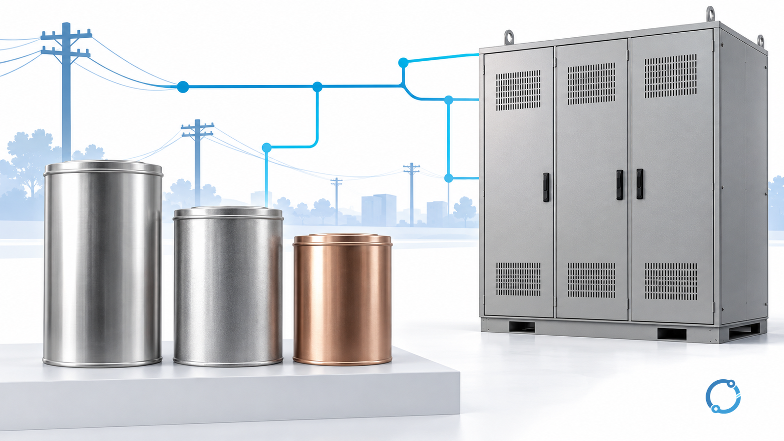
An automatic capacitor-bank panel has two different paths to understand: the power path that connects capacitor steps to the bus, and the sensing/control path that decides which steps to request. A controller’s “step on” command does not prove that the expected reactive output is present.
This article is a functional drawing-reading guide for industrial low-voltage alternating-current (AC) shunt power-factor-correction banks. It explains component duties and interfaces. It is not a terminal-by-terminal wiring diagram, capacitor-sizing study or permission to open an energized panel.
Start at the system boundary
Identify the bus the bank compensates, the loads included in the measurement boundary and the operating modes. Record utility supply, generator operation, local generation and any mode in which the bank must be disabled or controlled differently.
Keep the desired correction function separate from its implementation. The power-factor correction guide explains kW, kvar, target selection and harmonic limitations. A functional review assumes those design inputs have been established.
The International Electrotechnical Commission (IEC), in IEC 61921:2017, covers low-voltage AC shunt correction banks, potentially incorporating switching and control apparatus. IEC 60831-1:2014 addresses the relevant self-healing shunt-capacitor scope. A complete-bank assessment and a capacitor-unit assessment are different evidence boundaries.
Follow one step through the power path
On the approved drawing, trace the incoming arrangement, distribution within the panel, step protection, switching equipment and capacitor branch. Include a reactor where the actual design requires one; do not add a generic reactor percentage to every bank.
The diagram should establish what each device does, not merely display recognizable symbols. Protection clears specified faults. Routine switching connects or disconnects a step. Discharge arrangements address stored energy after disconnection. These duties are not interchangeable.
| Functional area | Question the drawing must answer | Evidence to retain |
|---|---|---|
| Incoming/distribution | Which source and bus feed the bank? | Defined operating modes and assembly basis |
| Step protection | What part of the circuit is protected? | Exact protected path and coordination |
| Switching | How is each step connected and disconnected? | Appropriate switching duty and control basis |
| Capacitor/reactor branch | What output and harmonic arrangement are intended? | Accepted step data and network study |
| Discharge | How is residual energy addressed? | Exact equipment instructions and safe-work procedure |
The APFC incoming MCCB guide owns selection of the automatic power-factor-correction (APFC) panel’s incoming molded-case circuit breaker (MCCB). Do not repeat its selection arithmetic to substitute for step-level review.
Trace sensing separately from step commands
A power-factor controller needs a measurement arrangement that represents the intended correction boundary. Identify its current-transformer (CT) input, voltage reference, polarity/phase relationships and scaling from the actual approved scheme. There is no universal CT terminal or placement instruction for every controller.
For example, a measurement boundary that excludes the bank’s own effect may not support the intended feedback strategy. Different control arrangements require different interpretations. Show which load and bank currents the measurement represents before evaluating a displayed power factor.
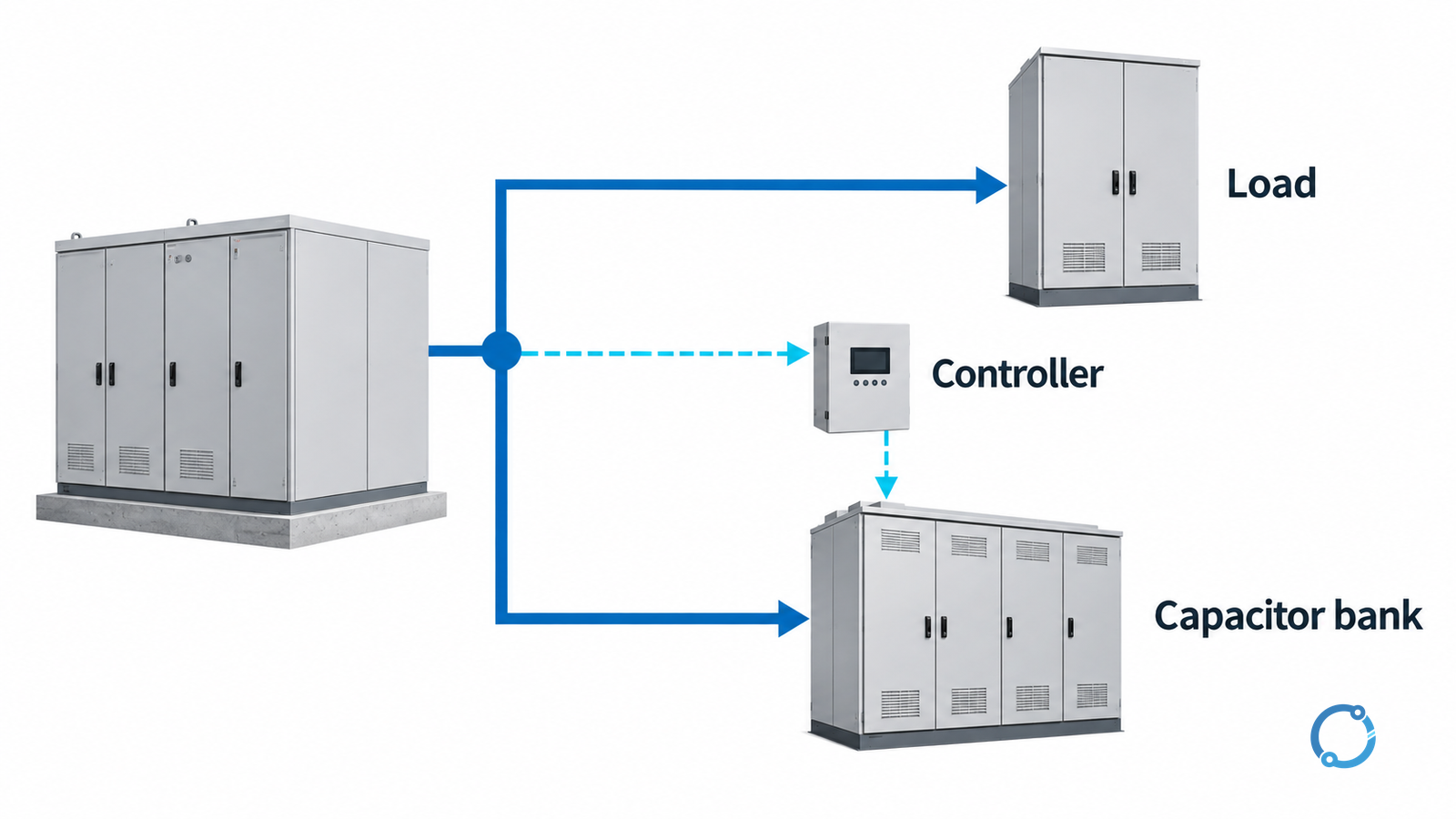
CT circuits require their own engineered safety and test arrangements. Use the CT installation and testing workflow for that boundary; do not improvise by disconnecting a CT secondary while operating.
Distinguish requested, connected and delivering states
Use separate columns for a step command, its accepted connection indication and evidence of output. A command can be present while the branch is unavailable. Conversely, unexpected connected output is not resolved by a reassuring controller screen.
Consider a hypothetical schedule of 10, 20 and 20 kvar at one stated voltage and frequency. All three total 50 kvar. Selecting the first and third nominally represents 30 kvar on that same basis.
The example is an accounting exercise, not a product rating or a guarantee of measured output. Voltage, actual branch condition, harmonics and the designed reactor/capacitor arrangement can affect operation. A sum of step labels cannot establish actual bank performance.
Do not use repeated switching as an informal diagnostic. Switching strategy, reconnection constraints and required residual-voltage conditions belong to the accepted design and equipment instructions.
Preserve thermal and stored-energy boundaries
Check that component losses, ventilation, ambient and enclosure arrangement remain within the complete assembly’s accepted conditions. A clean bank schematic does not prove that the cabinet can remove heat or withstand the location’s fault duty.
Capacitors can retain dangerous energy after the source is disconnected. The U.S. Occupational Safety and Health Administration (OSHA), in 29 CFR 1910.333, addresses hazardous stored electrical energy and capacitor treatment. Qualified personnel must follow the approved isolation, discharge and verification procedure. A controller command or an elapsed generic waiting time is not proof of a safe state.
The reading task is complete when the drawing identifies the compensated boundary, every power branch, sensing references, control authority and evidence for actual step behavior. Missing branch data or an ambiguous measurement boundary is a design hold, not something to resolve by guessing connections inside the panel.