
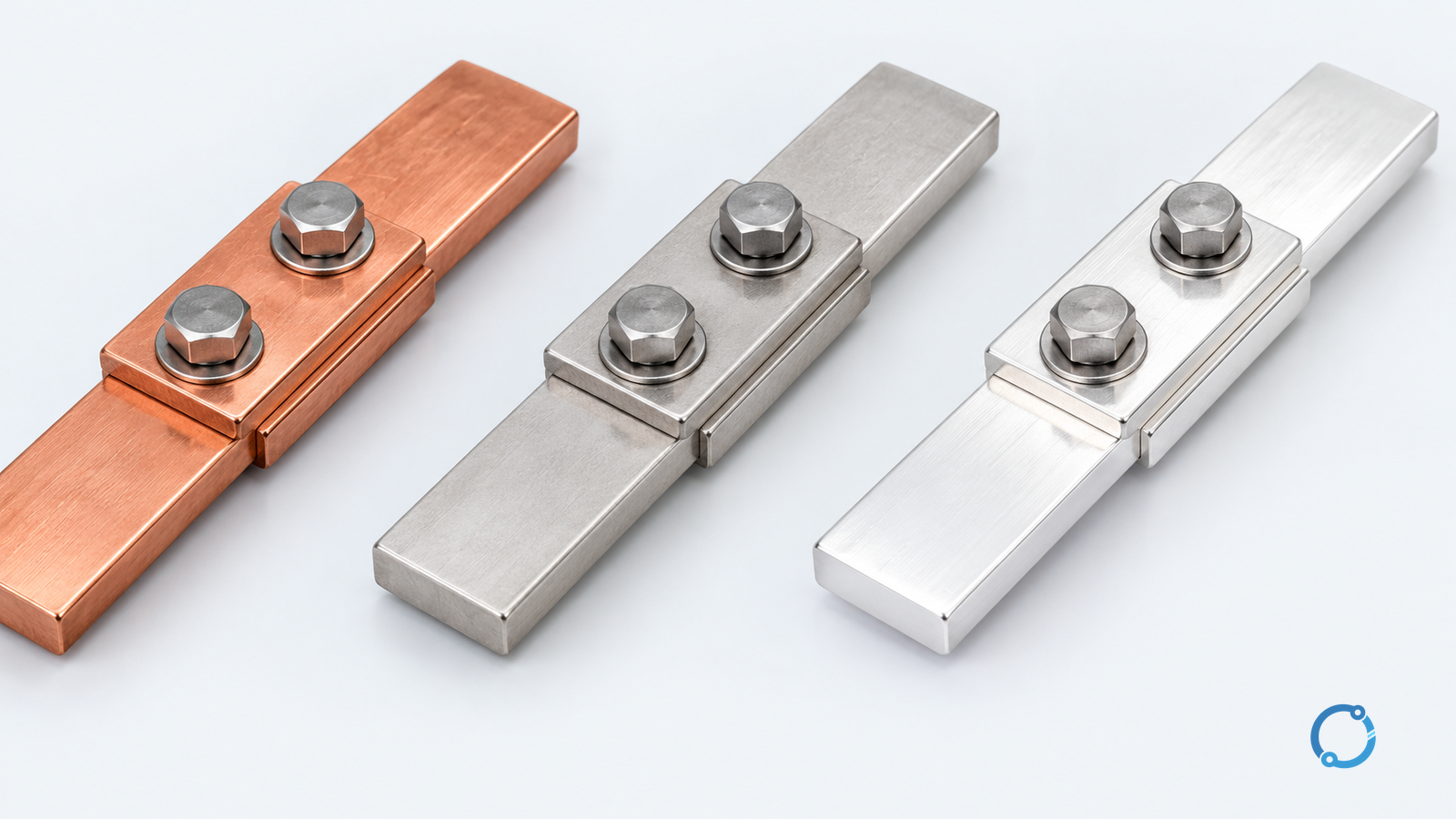
Choose a copper busbar finish from the joint outward. Bare copper can suit a protected, well-prepared copper-to-copper connection; tin plating can be considered where a tinned interface is specified and the complete coating system is controlled; silver plating can be considered where its contact and environmental behavior fit the approved design. None of those statements is a universal winner. The mating surface, contact pressure, micro-motion, atmosphere, cleaning and verification requirements decide whether a finish is appropriate.
This guide applies to the surfaces presented at low-voltage copper busbar joints. It does not replace bulk current sizing, temperature-rise testing or an assembly standard. Use the copper busbar ampacity and derating method for the conductor path and this page for the finish decision at its connections.
The decision starts at the interface
A busbar joint is a system within a system. The bar carries current through its bulk section, but the joint adds spreading resistance and an interface resistance where the surfaces meet. A useful conceptual model is:
Rpath = Rbulk + Rspreading + Rinterface
The equation is not a substitute for a tested joint. It separates three questions that a finish name can otherwise hide. Rbulk concerns conductor material and geometry. Rspreading depends on how current moves from the bar into the overlap. Rinterface depends on the real metal-to-metal contact area, films, pressure and the stability of those conditions over time.
The Copper Development Association’s busbar design and installation guidance describes contact through discrete conducting spots rather than continuous contact across the whole apparent overlap. That model explains why a smooth-looking surface, a nominal contact area and a finish label are not enough evidence. The joint must be prepared and assembled as the approved construction.
A fixed-dimension comparison
The table compares the finishes under the same dimensions. Each use case is conditional, not a ranking.
| Decision dimension | Bare copper | Tin plating on copper | Silver plating on copper |
|---|---|---|---|
| Surface role | Copper meets the mating surface directly | A tin-rich surface changes the interface or corrosion behavior | A silver-rich surface changes the interface or corrosion behavior |
| Strongest use case | A protected, specified copper-to-copper joint with controlled preparation and pressure | A defined tinned connection with an approved coating system and mating surface | A specified silver-compatible connection whose contact and exposure requirements justify it |
| Main concern | Oxidation, tarnish or contamination can alter an inadequately prepared interface | Tin can wear, flow or form films; closely spaced pure electroplated tin needs a whisker check | Silver can tarnish in sulfur-bearing environments; discoloration requires assessment |
| Pressure and preparation | Approved flatness, cleaning, pressure and assembly remain essential | Coating continuity and maintained pressure are essential | Coating adhesion, mating finish and the specified process are essential |
| Micro-motion | Fretting can damage the copper interface | The softer surface may wear differently; verify the actual contact system | Motion and film formation still require verification |
| Inspection | Check contamination, damage and joint stability by approved methods | Check specified coverage and adhesion; do not infer quality from color | Check coverage, damage and tarnish with electrical evidence |
| Main tradeoff | Direct simplicity can be offset by exposure and preparation sensitivity | Added process controls bring a different interface and possible substrate protection | Cost and process complexity require the right joint and environment |
| Release rule | Approve the joint against its specification | Approve the coating and assembled connection against product requirements | Approve the finish, mating system and service exposure against product requirements |
The comparison omits a “conductivity winner.” A finish is a thin layer on a larger conductor and joint, not a replacement for the bulk metal.
Bolted joints need stable pressure more than a finish slogan
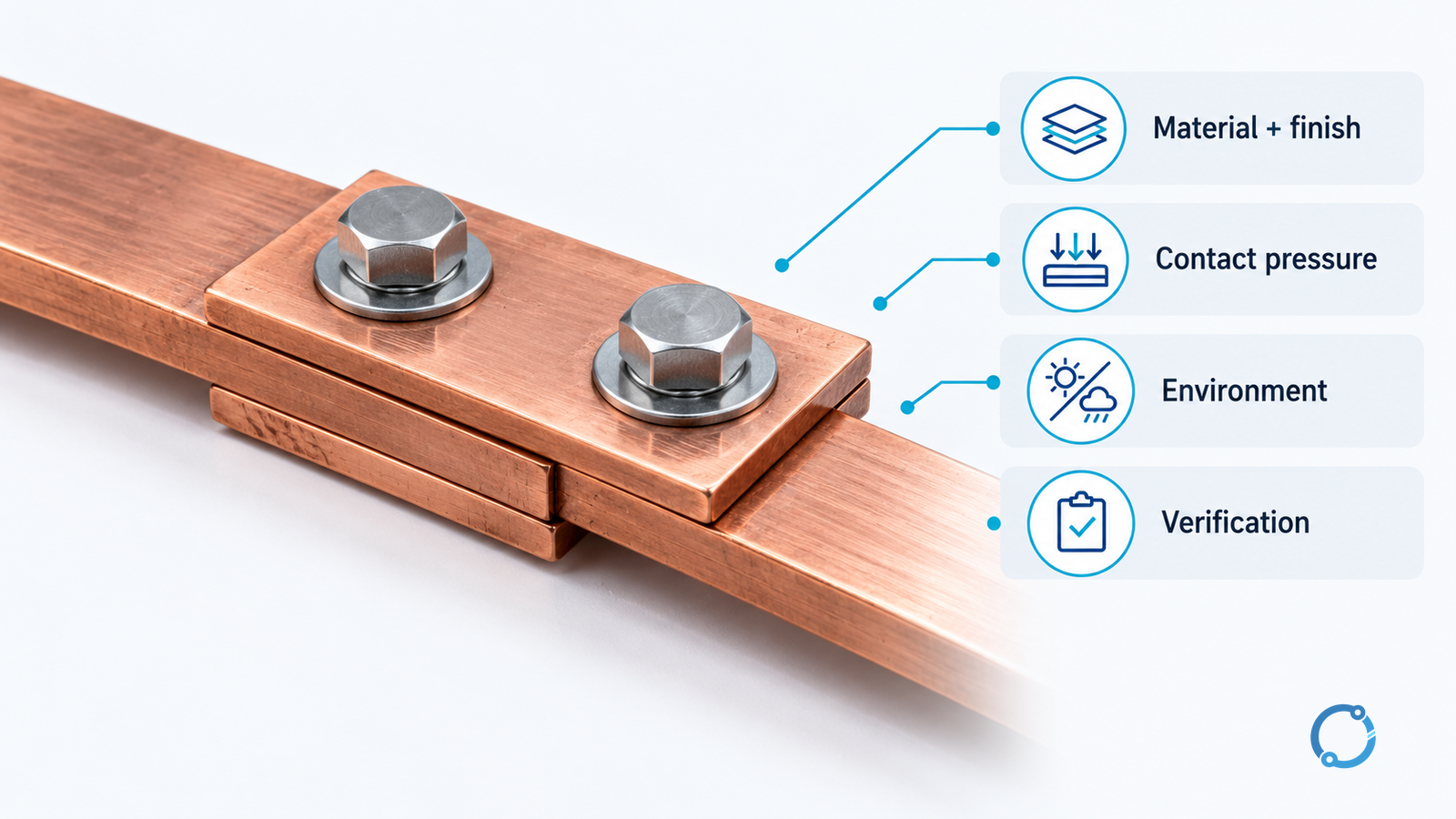
In a bolted joint, force transmitted through the overlap maintains contact. Flatness, burrs, overlap, bolt position, washers, torque, fastener material and thermal expansion can change the pressure distribution. A plating may alter friction or deposit stability, but it does not excuse poor alignment or uncontrolled tightening.
The Copper Development Association guidance notes that coatings can also introduce tradeoffs: soft plating may flow under pressure or temperature, and plated surfaces can change the way a copper-to-copper joint forms and remains stable. That does not make plating inherently wrong. It means the finish is part of a qualified construction, not a cosmetic add-on.
Establish the current path and hardware stack before comparing finishes. Identify the mating surface, its preparation, reinspection needs and whether assembly instructions distinguish bare from plated hardware. Suitability against one mating material does not establish suitability against another.
Preparation and coverage are part of the finish
A coating’s name says little about its quality. The substrate must be prepared, the coating continuous and free of pinholes or damage, and the finished part protected during handling and assembly. A damaged edge with exposed copper is not an intact coated interface.
Record the approved substrate, coating process, coating class or thickness where the product specification defines one, and the inspection method. Do not invent a universal thickness from an article. Assembly drawings, qualified test reports and the accepted process specification should carry those numbers.
Sliding and pluggable contacts change the problem
A bolted joint is normally intended to remain fixed. A sliding or pluggable contact deliberately moves during mating and may experience small relative movement while installed. That changes the surface-wear question. Fretting is accelerated surface damage under small oscillatory movement; the Copper Development Association explains that wear debris and oxidation can progressively alter the contact. NASA’s connector assessment likewise identifies contact movement as a mechanism to consider alongside plating compatibility and workmanship.
The NASA document concerns spacecraft connectors and is not a low-voltage busbar certification source. Its transferable lesson is limited but important: a connector or contact is an application-specific system. A finish-approved material list does not prove that the installed interface will remain clean, aligned and mechanically stable.
For a pluggable contact, define:
- the mating finish and the permissible material combinations;
- insertion and withdrawal requirements;
- allowable alignment, wear and contamination;
- the effect of repeated operation;
- the inspection and replacement boundary;
- the test evidence for the complete contact design.
Do not carry a bolted-joint finish recommendation into a sliding contact merely because both conductors are copper. The motion changes the failure mechanisms.
Soldered and welded connections are separate decisions
Plating compatibility in a bolted joint cannot be transferred directly to soldering, brazing or welding. Heat, flux, filler material, intermetallic formation and process control create a different metallurgical problem. A finish selected to protect a mechanical contact may not be the correct finish for a soldered termination, and a solderable coating may not be suitable for repeated mechanical mating.
Define the joining process first. Then obtain the manufacturer’s or qualified process instructions for that substrate and finish. The low-voltage cable termination guide is useful for the broader termination quality boundary, but it does not authorize a particular plating or joining method.
Corrosion depends on the exposure and the complete coating
Copper and silver can tarnish when exposed to sulfur-bearing atmospheres. A NIST investigation of corrosion in homes with problem drywall identified copper sulfide, silver sulfide and electrical-contact corrosion in the studied environment. That finding supports the need to identify sulfur exposure; it does not establish that every silver-plated busbar will fail, that tin will always be unchanged, or that one finish has a universal service life.
Visible tarnish is therefore neither an automatic rejection nor an automatic pass. A surface film may affect contact resistance, but the outcome must be evaluated for the specific interface. Historical NIST research on silver sulfide also cautions against assuming that every silver tarnish film behaves like a perfect insulator. The practical conclusion is narrower and more useful: inspect the assembled contact with approved methods and compare it with defined acceptance evidence.
Corrosion selection should account for:
- Humidity and condensation cycles. Wetting can concentrate contaminants and alter surface chemistry.
- Sulfur-bearing gases. Identify the exposure rather than relying on the color of the finished part.
- Salt or chloride exposure. Check the enclosure and product evidence; a decorative coating does not establish environmental protection.
- Mating-material compatibility. Two acceptable finishes are not necessarily an acceptable pair.
- Coating damage. Edges, threads, contact marks and rework can expose the substrate.
- Cleaning and maintenance. Aggressive cleaning may remove protection or leave residues.
For assemblies within its scope, IEC 61439-1:2020 provides a general framework for low-voltage switchgear and controlgear assemblies, including characteristics, construction and verification. It does not select a finish or replace a product standard, design drawing, test plan or local adoption requirement.
Why silver plating is not automatically the coolest
Silver has a lower bulk resistivity than copper, but a silver plating is thin and sits at selected surfaces. The temperature of a finished joint depends on the total current path, the actual contact area, contact pressure, fastener behavior, surrounding conductors, ventilation and enclosure conditions. A lower-resistivity surface cannot compensate for a loose joint, a damaged coating or restricted heat transfer.
A finish can change contact resistance, friction, wear, film behavior and assembly. Those effects may improve or worsen the complete connection. Temperature rise is an outcome to verify, not a property to infer from a finish name.
AC effects are conditional
Alternating current crowds toward the surface of a conductor, and nearby conductors can create proximity effects that change effective resistance. IEEE’s skin-effect orientation page describes the basic mechanism. The important boundary is scale: the plating is generally much thinner than the relevant skin depth at power frequencies, so the finish alone does not determine the AC loss of a practical busbar.
Conductor shape, spacing, phase arrangement and the complete current path still matter. If a design uses high-frequency ripple, short current pulses or a compact multi-bar arrangement, the electromagnetic and thermal study must match the actual waveform and geometry. Do not use a plating claim to avoid that work.
Cost, inspection and rework
The lowest purchase price is not necessarily the lowest lifecycle cost. A finish may add material, bath or process steps, masking, inspection, packaging and rework controls. A bare bar may be cheaper to obtain but require different preparation and protection. A plated bar may require repair limits and approved touch-up procedures rather than an uncontrolled brush or chemical treatment.
Compare options on the same basis:
| Cost or process item | Record before selecting the finish |
|---|---|
| Material and coating | Approved material grade, coating system and acceptance specification |
| Fabrication | Cutting, bending, drilling and edge treatment before or after coating |
| Masking and contact zones | Which areas must remain uncoated or conductively finished |
| Assembly | Mating finish, hardware, torque or force method and required tools |
| Inspection | Coverage, adhesion, damage, dimensional and electrical checks |
| Maintenance | Cleaning limits, replacement rules and accessible inspection points |
| Rework | Approved repair method and the point at which replacement is required |
This is a selection record, not a price formula. For mass and material-cost calculations, use the separate busbar material-cost guide rather than assigning a plating premium without evidence.
An evidence-bounded selection workflow
Use this sequence when the product design has not fixed an approved finish.
1. Define the joint
Classify it as fixed bolted, sliding or pluggable, soldered or welded. Record current, voltage, duty, conductor size, mating material and environmental conditions. An inaccessible or repeatedly serviced joint is not a sealed permanent connection.
2. Establish the mating finish
Identify what touches the busbar. Compare compatibility at the interface, not two isolated material names. Plated hardware, washers, device terminals or a cable lug can each change surface behavior.
3. Define the mechanical process
State preparation, flatness, overlap, pressure or torque, hardware and assembly order. The process must be repeatable. A finish that depends on scratch-free handling, exact force or cleaning cannot be judged without those controls.
4. Screen the environment
List relevant humidity, condensation, salt, sulfur-bearing gases, dust and cleaning chemicals. Check whether enclosure and product evidence cover those conditions. A coating is not a blanket environmental rating.
5. Screen motion and service life
For a fixed joint, define micro-motion sources and inspection. For a sliding contact, use mating-cycle and wear evidence for the actual finish pair. A bolted-joint recommendation does not automatically survive repeated motion.
6. Obtain construction-specific evidence
Look for qualified resistance, temperature-rise, mechanical, corrosion and wear evidence as applicable. It should identify substrate, finish, coating class or thickness, mating material and test conditions. A generic “more conductive” statement is not a joint qualification.
7. Verify coating integrity
Use the approved inspection method. Confirm specified coverage, contact-area preparation and freedom from damage at edges, holes and assembly marks. Color alone cannot confirm thickness, adhesion or substrate exposure.
8. Release the complete connection
Release only when finish, mating surface, preparation, hardware and verification agree. Preserve that combination in assembly documentation. If an element changes, review the joint rather than assuming the finish remains interchangeable.
Stop conditions
Pause the selection and obtain engineering review when:
- the mating finish is unknown or changes between components;
- the joint relies on unspecified plating thickness, adhesion or coverage;
- the contact is exposed to sulfur, salt or condensation outside the product evidence;
- a bolted joint is subject to thermal cycling, vibration or repetitive rework without approved retention evidence;
- a sliding or pluggable contact uses a finish-pair or cycle history that has not been verified;
- exposed, closely spaced pure electroplated tin surfaces present an unresolved tin-whisker concern;
- visible tarnish is being accepted or rejected without a defined electrical and mechanical check;
- soldering, brazing or welding is being treated as a simple extension of a bolted-finish choice;
- the assembly cannot be inspected or maintained as assumed by the design.
NASA’s tin-whisker background explains why exposed pure electroplated tin deserves a specific construction review. The correct response is not to ban every tinned busbar; it is to establish the coating process, spacing, enclosure and qualified evidence for the actual design.
Verification should leave a traceable decision
A sound decision can be summarized in the joint record:
- busbar substrate and finish;
- mating finish;
- coating class or thickness where specified;
- preparation and cleaning method;
- contact pressure or tightening method;
- hardware and assembly sequence;
- environmental assumptions;
- relevant test or qualification evidence;
- inspection, maintenance and rework rules.
The final check is not whether the busbar looks bright or has the more expensive finish. It is whether the specified interface remains electrically and mechanically stable under defined service conditions. If that evidence is absent, the correct status is unverified, not “best.”
Sources
- Copper Development Association / European Copper Institute – Copper for Busbars: Guidance for Design and Installation
- NASA NESC – Spacecraft Electrical Connector Selection and Application Processes
- NASA NEPP – Tin whisker background
- NIST – Metallurgical investigations of corrosion damage in homes constructed with problem drywall (NISTIR 7809)
- NIST – Some electrical properties of silver sulphide
- IEEE – Skin effect
- IEC 61439-1:2020 – Low-voltage switchgear and controlgear assemblies – Part 1: General rules