
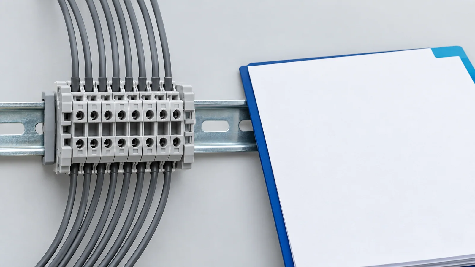
A marking on a terminal block is a starting point for verification, not permission to connect any wire that fits. Read the component identification, voltage and current ratings, conductor size and type, permitted wire count, preparation method, torque or tool instruction, and certification conditions as one set. Then check whether that exact component is acceptable in the finished panel. If any essential value is missing from the molded body, use the traceable product documentation or certification record; do not infer it from color, shape, or a similar part number.
This guide addresses industrial low-voltage copper-conductor terminal blocks and panel documentation. It does not decode every manufacturer’s proprietary symbols or establish that a complete panel complies with a particular national code.
Start with four different kinds of identification
Panel drawings and component markings solve different problems. Confusing them creates a plausible-looking but unverified installation.
| What you see | What it identifies | What it does not prove |
|---|---|---|
| Molded manufacturer or series mark | Product family and traceability | The exact current or wire range for every variant |
| Electrical rating | A stated use condition for the component | Finished-panel temperature rise or short-circuit rating |
| Terminal-position marker such as a circuit number | Connection location in a drawing | Product listing or electrical suitability |
| Conformity or certification mark | A claim that must be checked against its scheme and record | Unrestricted use in every jurisdiction or assembly |
The IEC 60445:2021 terminal-identification standard concerns identification and marking principles for equipment terminals and conductors. The IEC 60947-7-1:2025 terminal-block standard concerns industrial copper-conductor blocks within its defined scope. Neither catalog page certifies the unlabeled block in your hand.
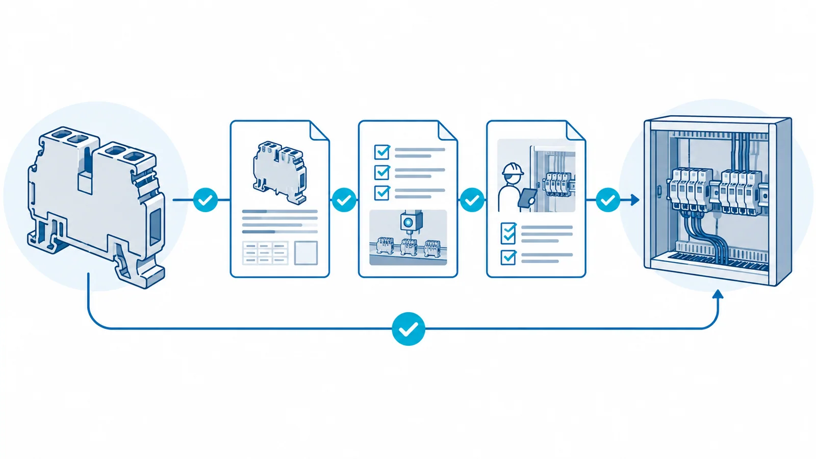
A mark-to-evidence crosswalk
Use the following sequence while the panel is de-energized and the exact part number is available. A slash or range in a marking may represent different conditions; the product’s legend controls.
| Item to check | Look on the block or packaging | Confirm in the exact record | Decision affected |
|---|---|---|---|
| Identity | Maker, series, part number, production code | Datasheet revision and certification entry | Is this the specified component? |
| Voltage | Rated value and AC/DC indication, if shown | Pollution degree, insulation conditions and applicable standard | Is insulation suitable for this circuit? |
| Current | Rated current, if shown | Conductor size, temperature and accessory conditions | Can this current path be used as designed? |
| Conductor | Size range, Cu/Al indication, solid/flexible acceptance | Stripping, ferrules, lugs and one/two-wire permissions | Is this particular wire preparation allowed? |
| Connection | Screw, spring, push-in, test-disconnect or PE function | Tool, insertion depth, torque, jumper and end-plate rules | Can it be assembled and tested correctly? |
| Approvals | Mark and file or control number | Official certificate/listing scope and conditions | Is the intended market and use covered? |
Do not convert a metric cross-section to AWG by visual guess. A converted nominal size is not automatically among the sizes tested with a specific clamping unit. Likewise, a terminal with room for two small wires is not necessarily identified for two conductors. In U.S. workplaces, OSHA 29 CFR 1910.303(c)(2) specifically calls for terminals for more than one conductor, and terminals used to connect aluminum, to be identified for that use.
Interpret ratings within their actual system
A rating is meaningful only with the conditions that produced it. A terminal’s current value does not replace conductor ampacity, overcurrent protection, enclosure thermal review, or the assembly’s short-circuit current rating. A voltage value does not alone establish sufficient clearance and creepage after jumpers, partitions, and adjacent devices are installed.
For an IEC-based industrial assembly, verify the component’s applicable standard and the finished assembly under the relevant part of the IEC 61439 series. IEC 61439-1:2020 sets general construction and verification requirements for low-voltage switchgear and controlgear assemblies; the applicable product part is used with it.
For a U.S. industrial control panel, verify the exact UL component category, conditions of acceptability where applicable, and the panel design rather than equating an IEC mark to a UL Listing. UL’s industrial control panel guidance explains the UL 508A context. The separate UL terminal-block compliance guide covers that approval decision in more depth.
Five frequent marking mistakes
1. Treating a terminal number as a rating
A clip-on marker such as X1:14 is normally a drawing reference. It says where the wire belongs, not how much current the clamp may carry. Verify the drawing revision and the component data independently.
2. Reading one value without the rest of the designation
Current, voltage, and conductor-size values can have different permitted combinations. Some accessories change usable conditions. Keep the full type designation, accessory set, and documentation revision together in the build record.
3. Assuming a universal conductor preparation
A stranded conductor might be accepted bare, with a ferrule, or with a particular ferrule profile depending on the clamping unit. A solid conductor may require a different insertion technique. The solid-versus-stranded terminal-block guide explains the mechanical difference; the product instructions decide the permitted preparation.
4. Treating a certification logo as the entire certificate
Check the file or database record, exact series, recognized/listed status, ratings, and any installation limitations. A logo on a sibling product or on packaging for another part number does not establish this component’s status. A standard’s title is not a product approval.
5. Losing identification after assembly
End plates, jumpers, covers, and wire ducts can hide identification or alter spacing. Final inspection must compare visible terminal markers, wiring schedule, and as-built drawings. The barrier terminal-block installation checklist provides a related hold-point method.
A safe reading workflow for the panel shop
Only qualified personnel should inspect or alter electrical assemblies. Before touching wiring, follow the local isolation procedure and verify the absence of voltage. For exposed fixed equipment in U.S. general industry, OSHA 1910.333 requires a qualified person to test the parts to which workers will be exposed before they are treated as de-energized.
- Identify the component. Record the complete part number, mounting variant, accessories, and production or revision mark if present.
- Locate the governing documents. Use the exact datasheet and installation instructions; obtain official certification evidence when approval is part of the panel specification.
- Map the circuit. Match the drawing’s terminal number, voltage, expected continuous current, conductor material and size, number of wires, and protective device.
- Check the connection method. Verify strip length, ferrule or lug acceptance, tool and torque, jumper use, end plates, covers, and temperature or environment limitations.
- Check assembly effects. Review grouping, heat, spacing, access, labeling, and the complete assembly’s required verification.
- Hold on discrepancies. Do not substitute a similar-looking block or reinterpret an unclear symbol on the shop floor. Resolve it with the exact document or design authority.
The result should be a short traceable record: part number, accepted use, drawing position, conductor specification, applicable approval evidence, installation instruction revision, and inspection sign-off. That record is more valuable than memorizing one symbol because it survives component substitutions and drawing revisions.
Sources
- IEC 60947-7-1:2025 — terminal blocks for copper conductors
- IEC 60445:2021 — identification of terminals and conductors
- IEC 61439-1:2020 — low-voltage assembly general rules
- OSHA 29 CFR 1910.303 — electrical equipment, connections and marking
- OSHA 29 CFR 1910.333 — electrical work practices
- UL Solutions — UL 508A requirements overview