
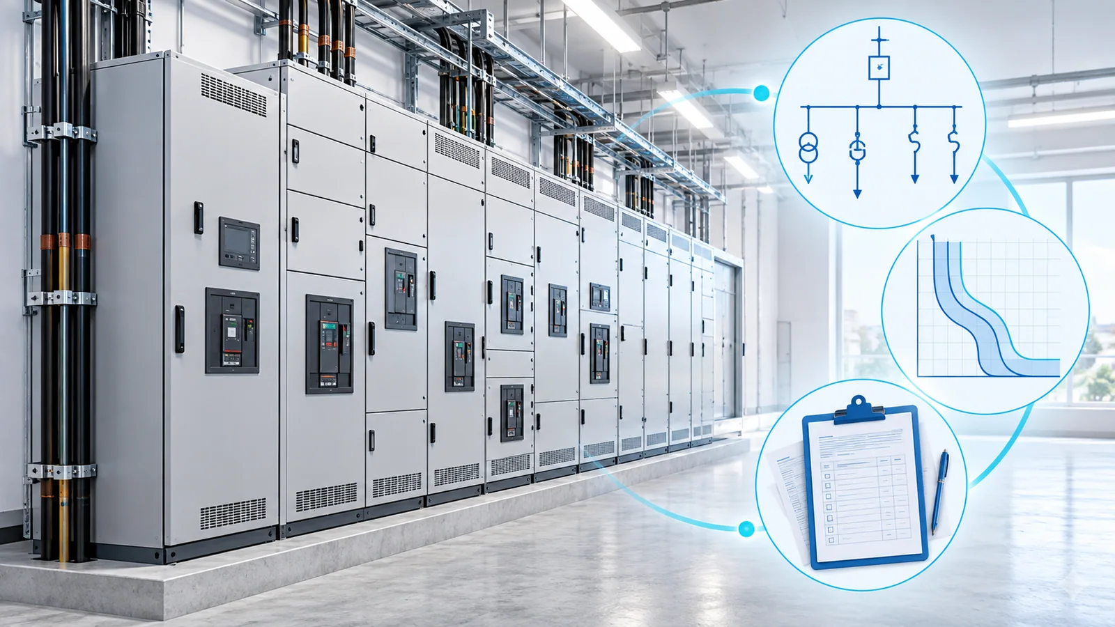
An arc flash study—more precisely, an incident energy analysis—models an electrical system to estimate the thermal energy a worker could receive at a defined working distance and to determine an arc-flash boundary for specified equipment and operating conditions. Those results support an arc-flash risk assessment, equipment labels, work planning, personal protective equipment (PPE) selection, and engineering decisions that can reduce exposure.
You may need a study now if none exists, the available report does not match the installed system, equipment or protective-device settings have changed, utility or generator fault-current data have changed, labels are missing or obsolete, or the study has reached its required review point. A study is not a one-time label project: it is a controlled engineering model that must remain aligned with the facility.
First, separate the study from the risk assessment
The terms are often used as though they mean the same thing, but they solve different parts of the safety problem.
| Item | Primary question | Typical output |
|---|---|---|
| Arc flash study or incident energy analysis | How much incident thermal energy and what arc-flash boundary are predicted for a defined scenario? | Calculation results, assumptions, equipment table, model files, and label data |
| Arc-flash risk assessment | Is an arc-flash hazard present for the task, how likely is an incident, how severe could it be, and which controls are required? | Task-specific risk decision, work controls, boundaries, PPE, job planning, and authorization |
| Short-circuit study | What fault current is available at each point in the system? | Fault-current results used for ratings, protection, and other analyses |
| Protective-device coordination study | How do protective devices operate together across relevant current levels? | Time-current relationships and settings that affect clearing time and selectivity |
The arc flash calculation depends on short-circuit current and protective-device clearing time, but it does not replace either study. It also does not decide whether energized work is justified.
In the United States, OSHA 29 CFR 1910.333 generally requires exposed live parts to be de-energized before work on or near them unless the employer can demonstrate that de-energizing creates additional hazards or is infeasible under the rule’s conditions. An incident-energy result must never be treated as permission to work energized.
What the calculation actually does
IEEE 1584-2018 provides mathematical models for estimating incident energy and arc-flash boundary for equipment within its scope. Its published scope covers three-phase AC systems from 208 V through 15 kV; it does not provide calculation models for single-phase AC or DC systems, and it does not prescribe PPE.
A competent study typically evaluates:
- available bolted fault current at each bus;
- estimated arcing current under the applicable model;
- protective-device clearing time at the calculated arcing current;
- equipment type, conductor configuration, enclosure dimensions, electrode gap, and working distance where required by the method;
- normal and alternate system configurations;
- generator, motor, and other rotating-machine contribution;
- multiple credible source and protective-device operating scenarios;
- the effect of maintenance switches, differential protection, zone-selective interlocking, or other energy-reducing functions when they are actually available and correctly applied.
The analyst should also test cases that can produce a lower arcing current but a longer clearing time. More available fault current does not always mean more incident energy: protective devices may operate faster at one current level and slower at another.
The five-stage study workflow
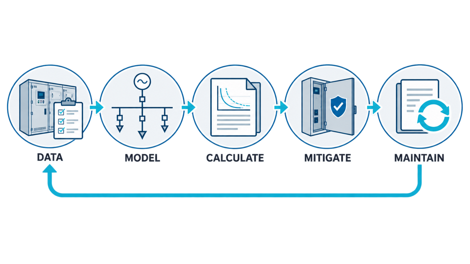
1. Define the scope and use cases
Identify the facilities, voltage levels, operating modes, equipment, tasks, and deliverables covered. The scope should state applicable standards and editions, system boundaries, owner responsibilities, field-data requirements, assumptions, exclusions, acceptance criteria, file formats, and review process.
IEEE 1584.1-2022 gives guidance for specifying the scope and deliverables of a study performed using IEEE 1584. This helps prevent a common failure: receiving labels without the calculation record, assumptions, editable model, or update process needed to maintain them.
2. Collect and verify field data
The one-line diagram is the starting map, not proof of the installed condition. Field collection may need to confirm:
- utility service and available fault-current data;
- transformers, generators, motors, and other sources;
- conductor sizes, lengths, materials, and routing assumptions;
- switchgear, switchboards, panelboards, motor-control centers, and other equipment types;
- fuses, circuit breakers, relay functions, trip-unit settings, and current transformer ratios;
- equipment enclosure and electrode configuration data required by the selected model;
- normal-open ties, alternate sources, emergency generation, and operating modes;
- maintenance modes and other energy-reducing controls;
- equipment condition issues that may make data collection unsafe or unreliable.
Field work must follow qualified-person, isolation, lockout/tagout, absence-of-voltage verification, and site electrical-safety procedures. Do not open energized equipment merely to obtain study data without a justified and controlled work plan.
For facilities within its scope, IEEE 1584.2-2025 provides data-collection guidance and checklists for three-phase 50/60 Hz AC systems operating at 1000 V and below.
3. Build and validate the system model
The model should reproduce the installed distribution system and every relevant operating configuration. Validation includes checking voltage levels, transformer impedances, conductor data, protective-device types and settings, source contributions, topology, equipment parameters, and model warnings.
Assumptions must be visible. A technically polished report can still be unreliable if it uses guessed cable lengths, generic breaker curves, obsolete utility data, or a system configuration that operators never use.
4. Calculate, review, and reduce exposure
Calculate incident energy and boundary results using the selected method, then review outliers and counterintuitive cases. High results should trigger an engineering review rather than an automatic label print.
Potential risk-reduction measures include:
- de-energized work and improved isolation design;
- faster or more selective protection where coordination and equipment duties permit;
- differential protection, zone-selective interlocking, or energy-reducing maintenance settings;
- current-limiting protective devices when correctly applied;
- remote operation, racking, or switching;
- system reconfiguration or equipment replacement;
- changes that increase working distance or remove the worker from the hazard zone.
Every mitigation must be re-modeled. Faster clearing can affect coordination, process continuity, and equipment protection, while a topology change can alter both available current and clearing time.
5. Deliver, communicate, and maintain
The completed work should connect engineering results to field use. Typical deliverables include:
- a report describing scope, standards, methods, assumptions, exclusions, and limitations;
- updated one-line diagrams and an equipment/result schedule;
- short-circuit and coordination information needed to support the arc flash results;
- incident energy and arc-flash boundary results for relevant scenarios;
- protective-device settings and a controlled record of proposed changes;
- equipment-label data and a label installation register;
- prioritized mitigation recommendations;
- the native model and supporting data files;
- a process for management of change, periodic review, and worker communication.
Labels are the field-facing summary, not the study itself. If the model, assumptions, and source data cannot be retrieved, the facility cannot efficiently verify whether a label remains valid.
Why might you need one now?
You have no defensible system-specific results
Generic PPE tables, inherited labels, software screenshots, or an old contractor spreadsheet are not substitutes for a documented analysis when the selected safety method requires system-specific incident-energy results. OSHA’s arc-flash hazard page emphasizes that arc hazards are not limited to high voltage and connects arc-flash protection with electrical safe-work practices.
The electrical system has changed
Revisit the study when a change could affect fault current, arcing current, clearing time, equipment geometry, working distance, or operating mode. Examples include:
- a new or replacement utility transformer;
- revised utility fault-current data;
- added generators, large motors, solar, storage, or other distributed energy resources;
- changed feeder conductors or transformer impedance;
- new switchgear, motor-control centers, or panelboards;
- breaker, fuse, relay, trip-unit, or current-transformer replacement;
- changed protective-device settings or firmware-dependent protection functions;
- normally open ties that are now operated closed;
- altered maintenance modes, interlocks, or differential zones;
- plant expansions and changed one-line topology.
Your study or labels no longer describe field conditions
Compare equipment identifiers, protective-device settings, source configuration, and one-line diagrams with the report. A label can be physically intact and still be wrong. Missing equipment, hand-modified settings, undocumented temporary feeds, or labels that reference retired equipment are management-of-change failures.
The study is due for review
NFPA 70E 2024 is the current published edition of the workplace electrical-safety standard at the time of writing. Its arc-flash risk-assessment framework calls for review when changes may affect the results and at a defined periodic interval. Confirm the exact requirement against the edition adopted by the organization or jurisdiction; do not assume that buying new labels resets the review process.
The original study used obsolete methods or incomplete data
A study based on an older calculation model may need reassessment, particularly where the installed equipment falls within the expanded variables of IEEE 1584-2018. An update should not merely import the old model and reprint labels: verify field data, device curves, equipment parameters, utility information, and operating modes first.
You are planning a shutdown, expansion, or capital project
A planned outage provides a safer opportunity to collect inaccessible nameplate, conductor, setting, and equipment-geometry data. Performing the analysis during design can also identify protection and equipment changes before construction, when mitigation is usually easier to integrate.
What an arc flash study cannot prove
An arc flash study does not:
- predict that an arc flash will or will not occur;
- certify that equipment is safe or compliant;
- replace preventive maintenance or equipment-condition assessment;
- replace lockout/tagout or absence-of-voltage verification;
- justify energized work;
- select PPE without the surrounding risk-assessment and work-practice framework;
- cover systems or scenarios outside the calculation method’s scope without another defensible method;
- remain valid after material system changes unless the model is reviewed and updated.
The CDC/NIOSH electrical-safety guidance states that electrical work should be assigned to qualified persons and emphasizes de-energization, energy control, verification, insulated tools, and appropriate PPE. A calculation supports these controls; it does not replace them.
How to judge whether a proposal is complete
Before commissioning a study, ask:
- Which facilities, buses, equipment, and operating modes are included?
- Which standards, editions, and calculation methods will be used?
- Who collects and verifies field data, and how will unsafe access be handled?
- Are short-circuit and coordination reviews included or separately supplied?
- Will the study evaluate low-current or long-clearing-time cases and alternate configurations?
- Which assumptions and exclusions will be documented?
- Are mitigation modeling and setting-change records included?
- Will the owner receive editable model files, result tables, one-lines, label data, and a management-of-change process?
- Who performs the independent technical review?
- What event or interval triggers the next review?
The practical decision
You need an arc flash study when workers may interact with electrical equipment and the organization’s selected safety method requires system-specific incident-energy information. You need it now when the system has no reliable study, the installed system has diverged from the model, changes could affect the results, or the formal review point has arrived.
Begin with scope and data quality—not labels. The useful outcome is a maintainable engineering model tied to safer work planning and a prioritized path for reducing exposure.
Sources
- IEEE 1584-2018 — Guide for Performing Arc-Flash Hazard Calculations
- IEEE 1584.1-2022 — Scope and Deliverable Requirements for an Arc-Flash Hazard Calculation Study
- IEEE 1584.2-2025 — Arc-Flash Study Data Collection Guide and Checklists
- NFPA 70E 2024 — Standard for Electrical Safety in the Workplace
- OSHA 29 CFR 1910.333 — Selection and Use of Work Practices
- OSHA — Electric-Arc Flash Hazards
- CDC/NIOSH — Electrical Safety in the Workplace