Short answer
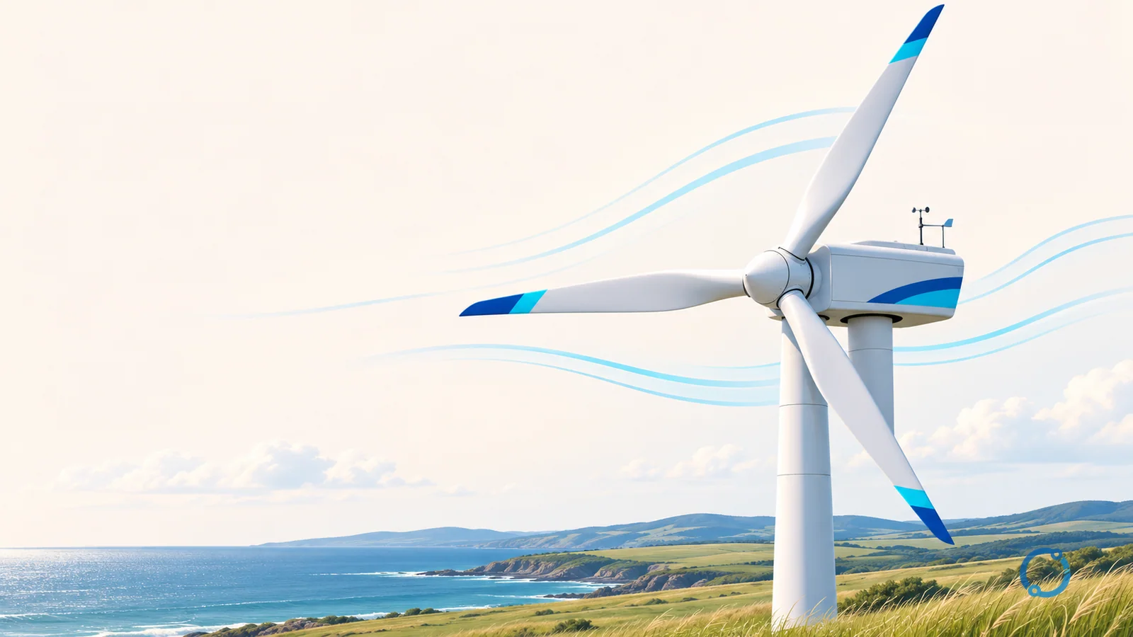
A wind turbine is not literally an electric fan running backward. A fan uses electrical energy to create moving air. A turbine uses moving air to create mechanical rotation and then electrical energy. The rotor blades act as aerodynamic lifting surfaces. Wind flowing across them produces a pressure difference, and the resulting lift turns the rotor with useful torque.
The machine can be followed as a chain of energy conversions: the kinetic energy of the wind becomes rotating mechanical energy in the rotor, the drivetrain transfers that rotation to a generator, and the generator produces electrical power. A geared turbine increases shaft speed before the generator. A direct-drive turbine avoids the gearbox and uses a large low-speed generator. Both arrangements turn the same external resource into electricity. The electricity-generation overview explains how wind fits alongside other generation sources, while this article stays focused on the machine itself.
The whole machine at a glance
A modern horizontal-axis wind turbine is easiest to understand as a set of systems rather than a single rotating object.
- Rotor: the blades and hub. It captures aerodynamic force and produces the low-speed, high-torque rotation.
- Blades: shaped like large airfoils. Their angle, twist and surface profile are selected to extract energy across a range of wind conditions.
- Hub: the central structure that carries the blades and connects them to the rotor shaft.
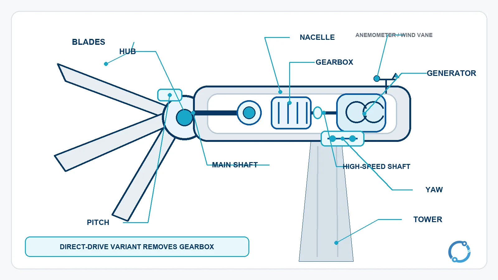
- Nacelle: the housing at the top of the tower. In a geared design it contains the main shaft, gearbox, high-speed shaft, generator, brake and control hardware.
- Main shaft and bearings: transmit the rotor torque into the nacelle while supporting the rotating mass.
- Gearbox: increases speed from the slow rotor to the generator shaft in a geared architecture.
- Generator: converts mechanical rotation into electrical power.
- Tower: supports the rotor and nacelle at height, where the wind is generally stronger and less disturbed by terrain.
- Yaw system: rotates the nacelle around the tower axis so an upwind rotor faces the changing wind direction.
- Pitch system: changes the angle of each blade to control aerodynamic torque and rotor speed.
- Anemometer and wind vane: measure wind speed and direction for the controller.
- Brake: holds the rotor after shutdown, particularly for maintenance. Blade pitch is the main aerodynamic means of stopping energy capture on many large turbines.
This component map is descriptive, not a universal construction drawing. Direct-drive turbines combine or omit several drivetrain parts, and small turbines may use a tail vane instead of a motor-driven yaw system. The useful principle is that every successful design must capture aerodynamic force, manage structural loads, control speed and transfer torque to a generator.
Why the blades turn
A turbine blade is not designed like a flat paddle that catches the wind and gets pushed backward. Its cross-section is an airfoil. As air flows around the curved shape, the pressure on one side becomes lower than the pressure on the other. The pressure difference creates lift and drag. The lift component is what turns the rotor.
The flow is more complicated than a simple pressure difference. The blade also changes the direction and speed of the air passing through the rotor disc, and the resulting aerodynamic force has both useful and unwanted components. Engineers care about lift-to-drag ratio, blade twist, airfoil choice, structural stiffness and the local wind angle along the span.
The blade angle is controllable on many large turbines. At low wind, the pitch setting can present the blades at an angle that produces useful lift. As wind rises, the angle can be adjusted to keep rotor speed and power within design limits. At extreme wind, the blades can be feathered so they produce very little turning force.
Most large horizontal-axis turbines use three blades. That is a system compromise among aerodynamic smoothness, structural loading, manufacturing cost and visual scale. It is not an aerodynamic law that forbids other blade counts. Two-bladed and multi-bladed turbines exist, and small machines can use different geometries.
A checked tip-speed example
Rotor speed can look deceptively slow when viewed from the ground. The blade tips travel much faster because they are far from the center.
Consider a hypothetical rotor with a diameter of 120 m turning at 15 rpm. The radius is:
r = 120 m / 2 = 60 m
One revolution carries a tip around a circumference of 2 x pi x r. At 15 rpm, the rotor completes 15 / 60 revolutions per second, so the tip speed is:
v_tip = 2 x pi x 60 m x 15 / 60
v_tip = 94.25 m/s, approximately 94 m/s.
Converting meters per second to kilometers per hour:
94.25 m/s x 3.6 = 339.3 km/h, approximately 339 km/h.
This is a teaching example, not a claim that every 120 m rotor turns at exactly 15 rpm. The calculation shows why blade-tip speed matters even when the hub appears to rotate slowly. Tip speed influences aerodynamic noise, erosion, structural loading and the way the blade interacts with the incoming wind. The article mentions tip-speed ratio as the relationship between tip speed and wind speed, but does not expand it into a rotor-design method.
How much power is in the wind?
The available power in a moving air stream increases with the cube of wind speed and directly with the area intercepted by the rotor. A useful proportional form is:
P_wind proportional to A x v^3
The exact theoretical expression also includes air density and a coefficient of one half, but the scaling relationships are enough to explain the machine behavior.
If the wind speed rises from 5 m/s to 10 m/s, the ratio is 10 / 5 = 2. Because power follows the cube:
2^3 = 8
The available wind power in that stream is eight times greater at 10 m/s, assuming the same air density and swept area. This strong sensitivity is why a site with modest average speed differences can have very different energy potential. It is also why the turbine’s control system cannot treat every wind speed as interchangeable.
The rotor’s swept area is the area of the circle made by the blades:
A = pi x r^2
For the hypothetical 120 m rotor:
A = pi x (60 m)^2
A = 11,309.7 m^2, approximately 11,310 m^2.
If the diameter doubles while the proportions stay the same, the radius also doubles. Area increases with the square of the radius:
2^2 = 4
The larger rotor therefore intercepts four times the swept area. The structure must also carry much larger loads, so scaling a turbine is not a matter of enlarging every drawing by the same factor.
The Betz limit and real rotor efficiency
The kinetic energy cannot all be removed, because the air must still leave the rotor region. Albert Betz derived a theoretical maximum power coefficient of 16/27, or 59.3%, for an ideal wind-energy rotor. The U.S. DOE describes this as the maximum power coefficient that a theoretically perfect wind turbine can achieve.
The Betz limit is an upper bound. It is not a guarantee, a target that every turbine reaches or a value taken from a particular machine. Real turbines experience drag, wake effects, blade-tip losses, mechanical losses, generator losses and control compromises. Their power coefficient is therefore lower than the theoretical maximum and varies with wind speed and operating condition.
The rotor is followed by a drivetrain and generator, so even the aerodynamic power captured by the blades is not the same as electrical output. The useful design question is not simply “How large is the rotor?” but “How much of the available wind power can this complete machine convert within its structural, noise, control and grid constraints?”
From slow rotor to fast generator
The rotor of a large turbine turns slowly but produces high torque. Many conventional generators are more compact and economical when driven at a higher shaft speed. A geared turbine therefore uses a gearbox between the low-speed main shaft and the high-speed generator shaft. The gearbox multiplies speed while the mechanical power passes through the drivetrain.
The ratio depends on the turbine architecture and design. It is not a universal number, and this article does not assign one. The important relationship is:
mechanical power = torque x angular speed
The rotor provides high torque at low speed. The gearbox increases speed and reduces torque on the generator-side shaft, minus losses and dynamic effects. The generator then converts the high-speed rotation into electricity. The generator explainer shows how relative motion between a magnetic field and windings creates voltage.
A direct-drive turbine takes another route. The rotor is connected to a large, low-speed generator without a gearbox. The generator can use a large diameter and many magnetic poles to produce useful voltage at the rotor’s slow speed. That reduces the number of rotating mechanical stages, but it does not eliminate the need for careful structural support, cooling, control and generator design.
The relationship between frequency, pole count and speed explains the direct-drive idea:
f = P x N / 120
For a given electrical frequency, a generator with more poles can operate at a lower mechanical speed. The exact pole count and speed belong to the machine design; the equation shows why a large multi-pole generator can suit a slow rotor. Neither geared nor direct drive is automatically “better” for every site. The tradeoffs include mass, maintenance, generator size, reliability, cost and nacelle layout.
What happens after the generator?
The generator produces electrical power, but the turbine is not necessarily connected straight to the grid at the generator terminals. A converter may change the voltage and frequency of the generated power to match the grid, and a transformer raises the voltage for collection and transmission. Protection equipment clears faults and isolates equipment when required.
The inverter explainer covers the general DC-to-AC conversion principle used in many power-electronic systems, although the detailed electrical architecture of a wind turbine depends on its generator and converter type. The transformer explainer explains magnetic induction and voltage transformation. The generator circuit-breaker article covers a protection boundary that becomes important when the generator is part of a larger network.
This article stops at that interface. Converter control, grid codes, fault ride-through and collector-system protection are separate engineering topics and should not be inferred from the mechanical chain alone.
Yaw: keep the rotor facing the wind
An upwind turbine extracts power most effectively when its rotor faces the incoming flow. The wind direction changes with weather, terrain and nearby turbines, so the nacelle cannot be installed at one fixed angle and forgotten.
The wind vane measures direction, the anemometer measures speed, and the controller decides how the turbine should respond. The yaw system turns the nacelle around the tower axis using yaw drives and motors. The control system has to avoid excessive hunting and must manage the loads created when the rotor is misaligned with the wind.
Some turbines are designed to operate downwind. Their rotor can be pushed away from the wind, and the yaw arrangement may differ. The presence or absence of a particular yaw drive is therefore a design detail, not a universal definition of a wind turbine.
Pitch: control aerodynamic torque
The pitch system changes each blade’s angle relative to the wind. This is the main aerodynamic control for rotor speed and power on many large turbines.
At low wind, the blade angle can be set to produce useful lift. As wind increases, the controller can adjust pitch so the rotor extracts only the power allowed by the machine’s rating and operating limits. When the wind becomes too strong, feathering the blades reduces the aerodynamic torque. In a severe condition, the turbine can stop rather than fight the wind with a rotor that continues to absorb energy.
A brake is not a substitute for pitch control. On large turbines, the brake often holds the rotor after the aerodynamic torque has been reduced, especially during maintenance. The controller coordinates pitch, yaw, generator torque and braking so that no single system has to manage an uncontrolled machine.
Cut-in, rated and cut-out conditions
Wind turbines are often described using these operating boundaries:
- Below cut-in: the wind is too weak to support useful generation, so the rotor may remain stopped or turn very slowly.
- Between cut-in and rated operation: the turbine extracts available power while staying within its control and structural limits.
- Above rated wind: the controller limits aerodynamic and electrical power so the turbine does not exceed its design capability.
- At cut-out: the wind is high enough that the turbine shuts down or feathers its blades to protect the structure and equipment.
The exact cut-in, rated and cut-out wind speeds vary by turbine design, site, control strategy and standard. This article does not publish universal values because a number copied from one machine would not describe another.
Why a turbine may be standing still
A stationary turbine is not automatically broken. The first possibility is that the wind is too low for useful generation. The second is that the wind is too high and the machine has entered a protective shutdown. The third is scheduled or corrective maintenance, with the rotor locked and the pitch system placed in a safe state. The fourth is a grid or operator instruction, such as curtailment when the network cannot accept the available power or when the system needs another response.
For a rapid visual check, blade pitch, yaw position, controller status and site conditions all provide clues. But safety procedures must come from the turbine’s operating system and site rules. No one should approach or attempt to diagnose a stopped turbine from its external appearance.
A wind plant also depends on the weather in a way that differs from a solar plant. The solar-panel explainer describes a different energy-conversion chain, but both resources require forecasting, power conversion and grid coordination. Neither source can be judged only by whether it looks idle or bright at a particular moment.
A compact causal model
The complete chain can now be summarized without treating the turbine as a black box:
moving air -> blade lift and drag -> rotor torque -> shaft and gearbox or direct drive -> generator -> converter and transformer -> grid or load
Control systems act across that chain. Yaw aligns the rotor with the wind. Pitch controls the aerodynamic torque. Generator torque control and power electronics shape the electrical response. The brake and safety system manage shutdown and maintenance states.
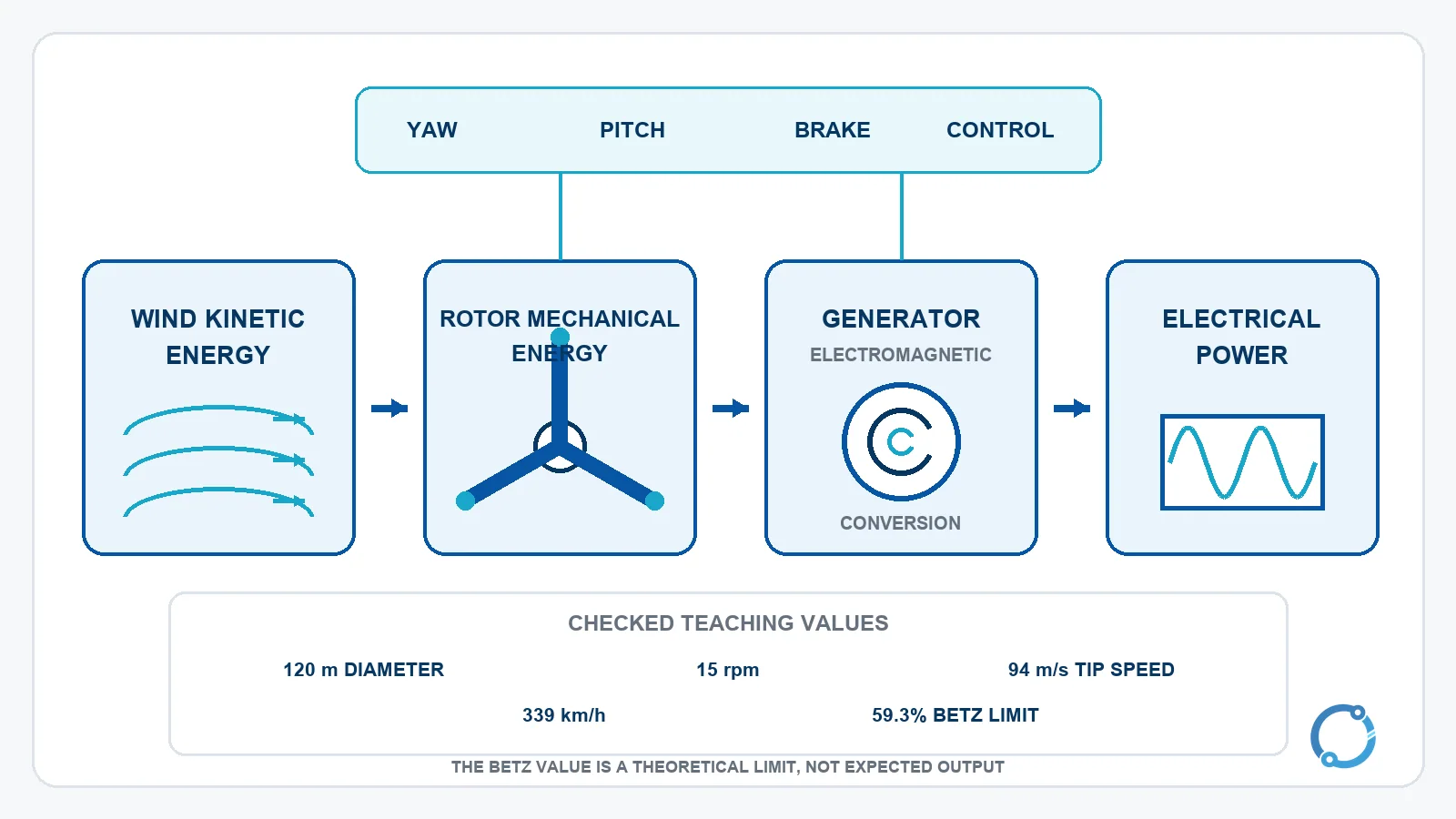
The next time a turbine appears to turn slowly, remember that the blade tips may be moving at a very high speed and that the control system is managing a machine with large aerodynamic, mechanical and electrical forces. The simple image of a rotating propeller is only the visible end of a carefully coordinated energy-conversion chain.
Frequently asked questions
Are wind-turbine blades pushed by the wind?
The useful force is mainly aerodynamic lift produced by pressure differences around the airfoil. Drag also acts on the blade, but the rotor is designed so lift provides the dominant turning effect.
Do all wind turbines have gearboxes?
No. Geared turbines use a gearbox to increase speed between the rotor and generator. Direct-drive turbines connect the rotor to a large low-speed generator and avoid a mechanical gearbox.
Why can a turbine be stopped while the wind is blowing?
The wind may be above the safe operating range, the turbine may be in maintenance, or the operator may have curtailed output for grid reasons. The controller and site procedure determine the actual cause.
Why is the blade-tip speed so much higher than the hub speed?
The blade tip travels around a much larger circle. Its tangential speed is proportional to radius times rotational speed, so a slow-looking hub rotation can still produce very fast tip motion.
What is the Betz limit?
The Betz limit is the theoretical maximum power coefficient for an ideal wind-energy rotor, equal to 16/27, or 59.3%. Real turbines operate below it because of drag, wake, mechanical and electrical losses.