Short answer: An inverter is a power-electronic device that converts direct current (DC) electricity into alternating current (AC) electricity. In a photovoltaic system, it sits between the DC modules or array and the AC loads, building distribution system or grid connection. It changes the form of the electrical energy; it does not create energy on its own.
That definition explains the name but not the engineering. An inverter has to switch, shape and regulate an output while remaining compatible with the source, load and, in many systems, the utility grid. This article follows the conversion path, explains the main inverter families and narrows the first capacity question to the information a designer actually needs.
Where an inverter sits in a photovoltaic system
A PV module produces DC. The module’s voltage and current vary with irradiance, temperature and the operating point selected by the power electronics. A PV array may connect modules and strings in series and parallel to obtain the intended DC voltage and current window.
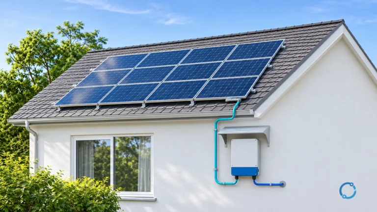
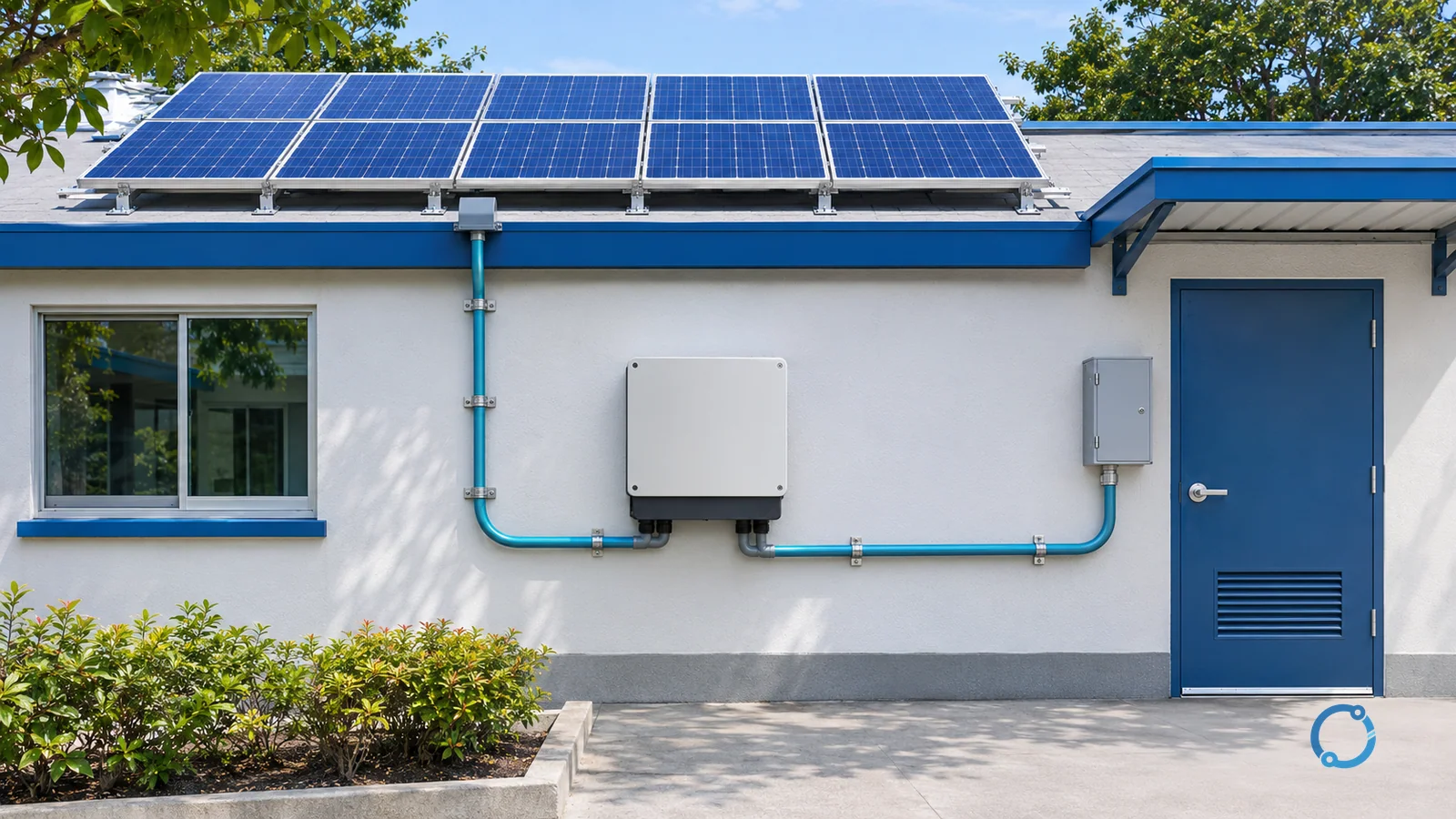
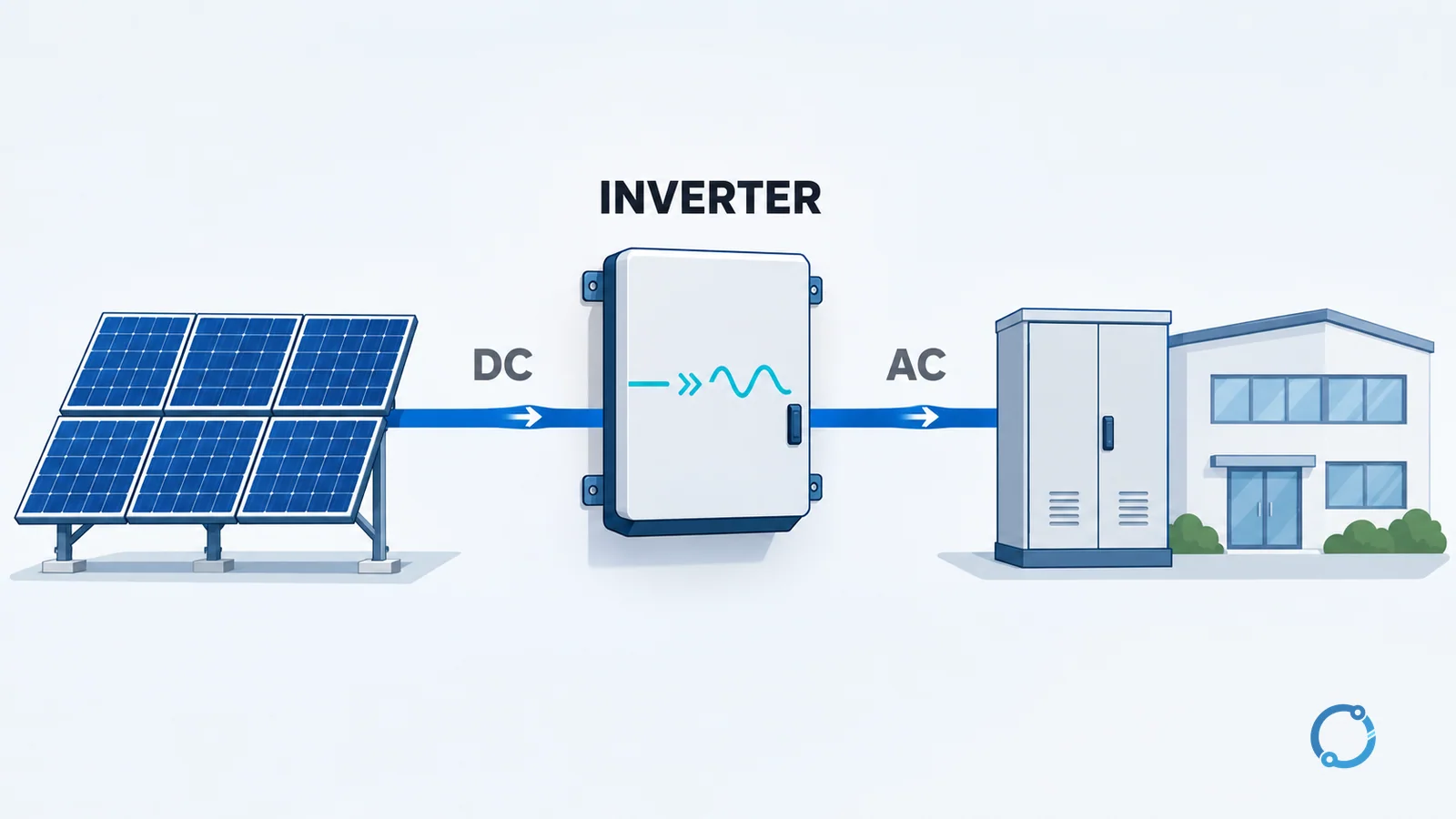
The inverter receives that DC input and provides an AC output. In a grid-tied system, the AC side connects to the building distribution system and the utility interface. In a standalone system, the AC output supplies local loads and may operate with a battery. The U.S. Department of Energy overview of solar integration describes the inverter as a device that converts the DC produced by solar panels into AC electricity, which the grid uses.
The equipment chain can therefore be summarized as:
PV modules or array -> DC conductors and switching/protection -> inverter -> AC distribution or grid
The exact components and protection depend on the system architecture, the local code and the equipment listing. The solar-panel principle article explains how the modules produce DC; this page begins at the conversion stage.
Why an inverter needs to switch
DC has a consistent polarity in the ordinary steady state, while AC periodically changes direction. An inverter cannot turn a steady DC source into AC through a passive transformer alone. It uses controlled switching to connect the DC input to the output circuit in changing patterns. The output is then filtered and controlled so that its effective voltage, frequency and waveform suit the load.
The DOE explanation describes a fundamental inverter action as switching the direction of a DC input back and forth very rapidly, with filters and other electronics used to produce a clean repeating AC waveform. Real products use different topologies, switching devices and control methods, but that description captures the central idea.
Common designs use insulated-gate bipolar transistors (IGBTs), metal-oxide-semiconductor field-effect transistors (MOSFETs) or other semiconductor switches. The inverter’s controller determines when each switch turns on and off. It also regulates the output against changing DC input and AC load conditions. The switching devices are not ideal: they have conduction and switching losses, thermal limits and voltage or current ratings that the design must respect.
Pulse-width modulation in plain terms
Pulse-width modulation (PWM) is a control technique in which the switching pattern is varied to synthesize an average output that follows a desired waveform. Instead of leaving a switch on continuously, the controller creates many short pulses. The widths of those pulses change over time. A filter and the behavior of the connected load smooth the pulse sequence into a waveform that approximates a sine wave.
The word “approximates” matters. The output contains switching components that the filter is intended to reduce. The final power quality depends on the inverter design, the filter, the load and the operating point. PWM is also used in motor drives and many other power converters; in an inverter, it is one part of the DC-to-AC conversion rather than a complete definition of the product.
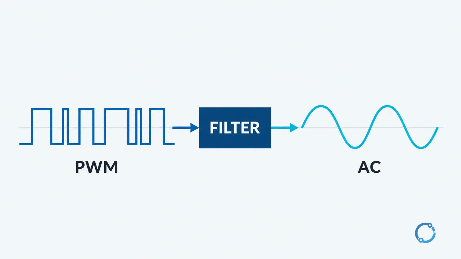
From a switching pattern to a usable AC output
A useful teaching model has three functional stages:
- DC input conditioning: the inverter accepts a DC voltage and may stabilize, boost or otherwise prepare it for the switching stage.
- Switching: semiconductor devices create a sequence of pulses or polarity changes.
- Filtering and control: the output is shaped, regulated and monitored so that it meets the inverter’s declared AC output specification.
Some inverters include an isolation transformer, some use a non-isolated topology and some use a high-frequency transformer. These are design choices with different implications for voltage relationships, isolation, size, efficiency and applicable installation rules. This article does not assume that one topology is universal.
The inverter also has a control interface. It may receive a start command, a power limit, a battery state-of-charge signal, a grid command or another operating instruction. The exact communication and protection functions depend on the product and the system. Grid-tied equipment has to be compatible with the local utility requirements; an inverter intended for a standalone system should not be assumed to have the same grid interface.
Pure sine wave and modified sine wave
An inverter’s output waveform is one of its most visible specifications. A pure sine-wave inverter produces an output that closely approximates a sinusoidal waveform. A modified sine-wave inverter produces a stepped or otherwise simplified waveform.
The labels describe the intended output shape, not a guarantee of compatibility with every load. Some equipment is designed for a sinusoidal supply and may operate poorly or overheat on a stepped waveform. Other equipment may tolerate a modified waveform within its own manufacturer’s stated limits. Motors, transformers, power supplies, clocks and sensitive electronics can respond differently because they use the supply in different ways.
For a specific appliance, follow the manufacturer’s input requirements and the inverter’s output specification. Do not infer compatibility from the words “pure sine” alone, and do not assume that an inverter with a modified output is suitable for every load that happens to run on AC.
The main inverter types
Inverter names often describe where the conversion takes place or what the product is designed to coordinate. These categories overlap, and manufacturers may combine functions in one enclosure.
String inverter
A string inverter receives DC from one or more strings of PV modules and converts it at a central point. It is a common architecture for residential and commercial PV systems. The array design must keep the DC voltage and current within the inverter’s input window, and the inverter’s AC output must match the site’s distribution and interconnection requirements.
The word “string” does not by itself describe the inverter’s control method, isolation or grid function. Those details come from the product documentation.
Microinverter
A microinverter performs DC-to-AC conversion at or near an individual module. The AC outputs of multiple units are combined for the building or grid connection. This architecture changes where conversion and monitoring occur, but it does not remove the need to design the AC circuit, protection and interconnection correctly.
Hybrid inverter
A hybrid inverter is generally designed to coordinate more than one energy source or sink, commonly PV, a battery and AC loads or the grid. The exact functions vary widely. Some products include battery conversion, backup outputs, energy management or generator inputs; others use the term differently. Verify the product’s interfaces and operating modes rather than assuming that “hybrid” means a particular feature set.
Off-grid inverter
An off-grid inverter forms an AC supply for a system that is not connected to the utility grid. It often works with a battery or another energy-storage element because the inverter needs a stable DC source when the PV array is not producing. Load management, battery limits and backup generation are system-level design questions, not properties of the inverter alone.
Grid-tied inverter
A grid-tied inverter operates with the utility system and must meet the applicable interconnection and power-quality requirements. Its control and protection functions may include synchronization, anti-islanding and grid-support behavior, depending on the product and the rules of the jurisdiction. The presence of a grid-tied inverter does not prove that an installation complies with those rules; the complete interconnection must be reviewed.
None of these categories is inherently the best choice. A string inverter can centralize equipment and maintenance; microinverters can distribute conversion; hybrid systems can integrate storage; off-grid systems can serve sites without a utility connection. The correct role depends on the source, load, storage, site and regulatory constraints.
Where maximum power point tracking fits
A PV array has an operating point at which it delivers the most power under the prevailing irradiance and temperature. Maximum power point tracking (MPPT) is the inverter control function that adjusts the array’s electrical operating point to seek that maximum. It sits inside the inverter’s DC-side control, but the algorithm it uses is not the subject of this article. The dedicated guide to MPPT algorithms for PV systems covers tracking methods and their operating assumptions; readers who need that level of detail should continue there.
Capacity and the DC/AC ratio
An inverter has an AC output rating and a DC input range. A PV array has a DC power rating under a stated set of test conditions, commonly the module’s nameplate or standard test condition value. A designer compares those values, but the comparison is more than a single division.
The DC/AC ratio is often described as the array’s DC power divided by the inverter’s AC power. A value above one can be intentional: the array may rarely reach its nameplate output because of irradiance, temperature and orientation, while the inverter is sized for a particular AC output and operating profile. A value that is too high for the inverter’s input limits or the site’s conditions can lead to clipping, where the inverter cannot process all available DC power. A value below one is not automatically wrong either; the useful answer depends on the array, inverter, load and energy target.
There is no universal ratio to copy from another project. Check the inverter’s maximum DC input power, DC voltage window, current limits, AC output rating and any product-specific design rules. The panel-count calculation guide handles the separate question of how many modules an annual-energy estimate may require; it does not replace an inverter’s electrical design review.
Efficiency: peak versus weighted
Every conversion stage has losses. An inverter’s efficiency is the useful AC output power divided by the DC input power under the stated operating conditions. Peak efficiency is the highest value achieved at a particular operating point. Weighted efficiency represents a defined mix of operating points and is intended to be more representative of a working profile.
The two numbers are not interchangeable, and a single peak-efficiency figure does not describe performance across the day. Datasheets define the test basis and the weighting method. Use those definitions and the product’s actual operating range rather than comparing headline percentages from different bases.
Efficiency also interacts with temperature, input voltage, load level and standby behavior. An inverter that is highly efficient at full output may have different performance at the low-load conditions that occupy many operating hours. The right comparison uses the expected production profile, not just one advertised number.
A practical sizing sequence
Sizing an inverter is a system exercise. A useful first sequence is:
- Define the DC source: module or array voltage, current and power under the relevant conditions.
- Define the AC load or grid interface: voltage, frequency, phase arrangement and expected demand.
- Check the inverter’s DC input window, maximum current and maximum DC power against the source.
- Check the inverter’s AC output rating against the load profile and any starting or surge requirements.
- Decide whether storage, backup, export limitation or grid support is required.
- Review efficiency at the expected operating points, not only at peak.
- Verify protection, isolation, cable and environmental requirements as part of the complete installation.
- Confirm the selected equipment and settings against the applicable product documentation and local rules.
This sequence is deliberately about inputs and boundaries rather than a universal capacity formula. A building with a steady load, a building with a highly variable load and an off-grid site with battery constraints can require different inverter behavior even when their nominal power values look similar.
The guide to how electricity is generated provides the larger context for AC sources and grid delivery. An inverter is a conversion interface within that system, not a replacement for generation, transformation or protection.
Common misconceptions
“An inverter is just a transformer”
A transformer transfers energy between AC windings through a changing magnetic field. An inverter uses active switching to create an AC output from a DC input. Transformers may be included inside an inverter, but the two devices perform different functions.
“A larger inverter is always better”
An oversized inverter may cost more, operate at low load for long periods or fail to match the source and protection design. An undersized inverter may limit production or be unable to supply the intended load. The useful choice depends on the array, load profile, input limits, AC requirements and the system’s operating strategy.
“A microinverter is right for every installation”
Module-level conversion has advantages in some layouts and maintenance models, but it is not a universal answer. String, hybrid, off-grid and grid-tied architectures solve different system problems. The site, shading, storage, service access, code requirements and equipment compatibility determine which architecture deserves evaluation.
FAQ
What does an inverter do?
An inverter converts DC electricity into AC electricity. In a PV system, it receives DC from the modules or array and supplies an AC load, building distribution system or grid connection, subject to its design and the system’s requirements.
How does an inverter turn DC into AC?
It uses controlled semiconductor switches to create a rapidly changing output pattern, then filters and regulates that pattern to produce the intended AC waveform. Different products use different topologies, but switching and output control are central to the conversion.
What is the difference between a pure sine-wave and modified sine-wave inverter?
A pure sine-wave inverter approximates a sinusoidal output, while a modified sine-wave inverter uses a stepped or simplified waveform. Compatibility depends on the connected equipment and its manufacturer’s input requirements, so the waveform label alone is not enough to approve a load.
What is MPPT in an inverter?
MPPT is a control function that adjusts a PV array’s operating point to seek the maximum available power under the current irradiance and temperature. The inverter may contain this function, but the tracking algorithm and its settings are a separate technical topic.
Does a higher DC/AC ratio always improve production?
No. A higher ratio can be intentional when the array rarely reaches its nameplate output, but it can also lead to clipping or exceed the inverter’s input limits. The correct value depends on the source, inverter, load, site conditions and verified design rules.